Wind Forces on Chimneys:
Having seen the stress distribution for any wall subjected to wind forces, let us assume the effect of wind forces on all of chimneys.
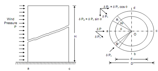
Figure illustrated a cylindrical chimney of height H, external diameters D, internal diameter d, subjected to horizontal wind pressure p as illustrated.
If γ refer to the unit weight of the masonry structure, direct stress because of the weight of the structure on its base f0 = γ H.

(a) Elevation (b) Cross-section
Figure
Assume a small strip of width R δθ, subtending an angle δθ at the centre and making an angle θ with the axis ac of the section,
δP = Wind force reaching the small strip
= p × R δ θ × H cos θ
= p H R δ θ cos θ
Element of the force normal to the strip,
δ Pn = δ P cos θ
= p H R cos θ × δ θ × cos θ
= p H R cos2 θ δ θ
Horizontal component of
δ Pn = δ P1 = δ Pn cos θ
= p H R cos3 θ δ θ
Another horizontal component of
δ Pn = δ P2 = δ Pn sin θ
Whereas summing up, this component gets cancelled out when we let a strip in the other quadrant as illustrated in Figure , while the components of Pn cos θ are added up.
∴ Net force in the direction X-X = 2δ Pn cos θ
= 2 p H R cos3 θ δ θ
Integrating over the entire exposed surface, from θ = 0o to 90o.
Total wind force

= p DH × (2 /3)= k × p DH
where, k = Coefficient of wind resistance, and
DH = Projected area of the curved surface.
BM because of wind force, M = PH /2
= p DH(2/3) × (H/2)
= p DH2 /3
Section modulus, Z = π (D4 - d 4 ) /32 D
Bending stress, f b =± M/ Z
Once you determine the bending stress, the extreme fibre stresses might be obtained by summing up with the direct stress due to self weight.