Vibration of Three Rotor Systems:
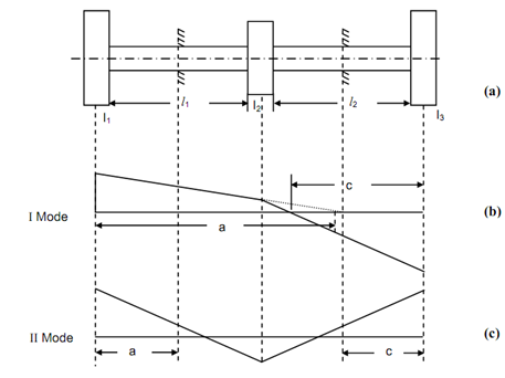
A three rotor system is illustrated in Figure (i). It shall have two modes of vibration that are illustrated in Figures (i) and (ii). One of the modes contains one node and other contains two nodes. The mode along 1 node is known as I mode and mode along two nodes is known as II mode. The I mode contain lower natural frequency and II node contain higher natural frequency. So it is a two degree of freedom system. The number of modes is equivalent to the degree of freedom.
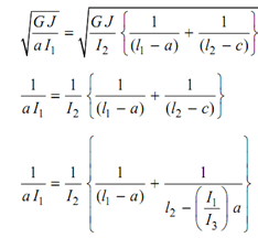
If we look at the II mode, it contains two modes and as we have completed in the last section consider the three rotors be imagined to be fixed at these sections. As there is no twist at these sections, so rotor shall continue to vibrate even after fixation. Now after fixation the rotor correspond to three single rotor systems. The expression for natural frequency may be written as:

and


As whole rotor vibrates with similar frequency at an instant,
∴ ωn1 = ωn2 = ωn3


( + I1 I3 + I1 I 2 ) a - l1 ( I1 I 2 - I1 I3 ) + l2 ( I 2 I3 - I1 I3 ) + I 2 I3 l1 l2 = 0
Equation (69) is a quadratic equation and will provide two values of 'a'. This shall provide two equivalent values of 'c'. The smaller values of these parameters is for II mode and greater value is for I mode. The modes might be plotted as:
(i) If a > l1, mode shall be as illustrated in Figure 18(ii). If a < l1, the mode point may be plotted in first segment. Decide amplitude of rotor 1 say 1 cm. Align this point along node point & draw a straight line until the location of rotor 2. Plot value of C. Align this point and location at rotor 2 and draw a straight line until the location of rotor 3. For a > l1, plot location of a. Align amplitude point on rotor 1 having this point and draw straight line until position of rotor 2.
Now plot C and align this point having point on rotor 2 and draw a straight line until location of rotor 3.
(ii) For II mode plot smaller value a, and amplitude of rotor 1 (Supposed value).
Align these two points and draw a straight line until the location of rotor 2. Plot C & align this point along point on rotor 2 and draw a straight line until the location of rotor 3. For measuring natural frequencies for these two mode put the two values of a in Equation.