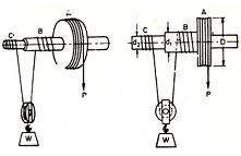
Differential Wheel and Axle:
Figure illustrates the block diagram of differential wheel and axle. The shaft is supported by the bearings at its ends. On this is mounted a formation contains three cylinders of difference diameters. It may either be forged with the shaft or these three cylinders may be keyed to the shaft. It is one of the most efficient lifting machines and extremely large amount of velocity ratio may be attained in this machine.
There are two strings or ropes. One of them is wound around the cylinder of the largest diameter as illustrated in Figure. The ends of other string are tied on the cylinders B and C, and the string is wound on both of them in the opposite sense. The winding of strings on cylinders A and C is in similar sense. As the effort is applied on one end of the string wound on A, it winds on cylinder B and unwinds from C at the same time. The load is mounted on the pulley which rests on the string as illustrated in Figure. The load is lifted up by application of effort because of the difference in diameters of B and C.

Let P is effort, W is load lifted, D is the diameter of largest cylinder A, d1 be the diameter of B, and d2 be the diameter of C.
Let the axle be rotated by one revolution, the net length of string wound
= π d1 - π d 2 = π (d1 - d 2 )
∴ The height by which the load is lifted = (π/2) (d1 - d2 ) .
The length of string unwound from cylinder A is πD.
Thus, velocity ratio,
V R = π D / (π/2) (d1 - d 2)
or V R = 2D /(d1 - d 2 )
Mechanical advantage M A = W/ P
Thus, efficiency,
η = MA / VR = W (d1 - d2 )/ 2DP
Therefore, η = W (d1 - d 2 ) /2DP