The Ideal Regenerative Rankine Cycle
The realistic ideal regenerative Rankine cycle is attained by extracting steam from the high-pressure turbine at different parts and is employed for heating the feed water. The machine where the feed water is heated is termed as regenerator. The regenerator as well de-operates the feed water that is essential to avoid corrosion in the boiler?
The feed water heaters of regenerators are categorized as open feed water heater and closed feed water heater.
Open Feed Water Heater:
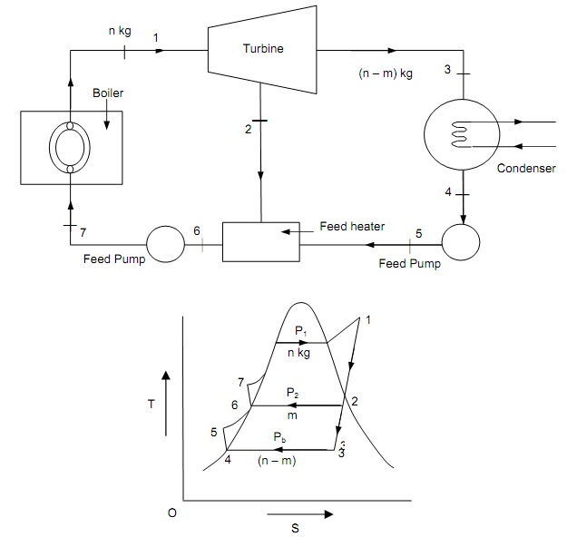
As shown in figure below the simple open feed water heater and the T-S diagram, is described that the working of regenerative cycle with different components.

Consider n kg of Steam flowing from the boiler to the turbine. Subsequent to expansion of n kg of steam of expanded to condenser pressure and quits the turbine at state-3. After condensation to state-4, the condensate water is enter to the heater maintained at similar pressure (n – m) kg of condensate mixed with ‘m’ kg of taken out steam and the mixture come out at stage-6. The latent heat of taken out steam has been employed to heat the feed water up to saturation temperature analogous to taken out steam pressure. Then n kg of heated condensate is pumped to the boiler where heating begins from state-7. This cycle is not ideal cycle as mixing in feed water heater is not reversible. Though with unlimited number of taken out steam parts, the mixing procedure become reversible and hypothetically Carnot efficiency can be achieved. The mass of bled steam (m) can be established by energy balance and mass balance equations applied to the feed heater.
This provides:
mh2 + (n - m) h5 = n h6
When pump work is neglected, h5 = h4
Then,
mh2 + (n - m) h4 = n h6
Knowing h2, h4 and h6, m can be established.
Total work done = W = n (h1 – h2) + (n - m) (h2 – h3)
Heat supplied = Q1 = (h1 – h6) neglecting pump work
The effectiveness of regenerative cycle is,
= [n (h1 – h2) + (n - m) (h2 – h3)] / (h1 – h6)

Figure: A Simple Regenerative Cycle