Rankine Cycle
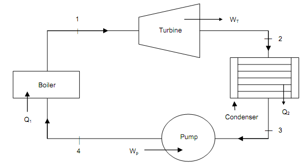
Rankine cycle is the simplest and an ideal cycle for vapor power cycles. Rankine cycle consists of four components and four thermodynamic procedures. Therefore each one of the procedure occurs in each constituent. The four constituents are shown in figure as follows.

Figure (a): Rankine Cycle Components and System

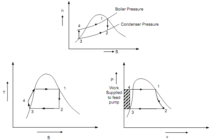
Figure (b): Rankine Cycle on T-S, p-v and h-s Diagram
The four procedures occur in rankine cycle are as follows:
• The procedure 1-2 is isentropic expansion in the turbine,
• The procedure 2-3 is isobaric reversible heat refusal in the condenser,
• The procedure 3-4 is a reversible adiabatic compression takes place in pump, and
• The procedure 4-1 is an isobaric heat addition procedure in the boiler.
To analyze and determine the effectiveness of rankine cycle by taking functioning fluid as water (1 kg) flowing via all the components of rankine cycle system. By noticing the rankine cycle in P-V, T-S and H-S diagrams as shown in figure (b) above for computing the efficiency of the rankine cycle.
The heat supplied = Q1 = (h1 – h3) – Wp
Here Wp = (h4 – h3) is termed as pump work per kg steam.
The heat discarded into the condenser = Q2 = (h2 – h3)
Total work done per kg of steam W = Q1 – Q2 = WT – WP = (h1 – h3) – WP
Here WT = turbine work

Whenever pump work is negligible, the Rankine cycle efficiency will be,
ηR = (h1 – h2) / (h1 – h3)
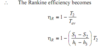
The expression of thermal efficiency can as well be build up by introducing thermodynamic mean temperature of heat adding together. Thermodynamic mean temperature of heat addition,

When pump work is neglected then,
Tav = (h1 – h3) / (S1 – S3)
