Pneumatic Actuators:
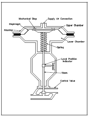
A simplified diagram of a pneumatic actuator is display in Figure. It operates through a combination of force established through air and spring force. The actuator positions a control valve through transmitting its motion by the stem.
A rubber diaphragm divided the actuator housing into two air chambers. The upper chamber receives supply air by an opening within the top of the housing.

Figure: Pneumatic Actuator: Air-to-Close/Spring-to-Open
The bottom chamber holds a spring which forces the diaphragm against mechanical stops within the upper chamber. At last, a local indicator is linked to the stem to denote the position of the valve.
The position of the valve is controlled through varying supply air pressure within the upper chamber. This output in a varying force on the top of the diaphragm. Initially, along with no supply air and the spring forces the diaphragm upward against the mechanical stops and holds the valve fully open. As supply air pressure is raised from zero, its force on top of the diaphragm begins to overcome the opposing force of the spring. That causes the diaphragm to move downward and the control valve to close. Along with increasing supply air pressure, a diaphragm will continue to move downward and compress the spring until the control valve is fully closed. On the other hand, the spring will begin to force the diaphragm upward and open the control valve if supply air pressure is decreased. In addition, if supply pressure is held constant at a few values among zero and maximum then the valve will position at an intermediate position. Thus, the valve could be positioned anywhere among fully open and fully closed in response to changes in supply air pressure.