Controlled potential electrolysis:
The controlled potential electrolysis apparatus is display in Figure. It consists of two independent electrode circuits which share a general electrode, the working electrode at that the analyte is deposited. An electrolysis circuit consists of a dc source (an l2 V battery), a potential divider which allows continuous variation within the potential applied across the working electrode, a counter electrode commonly platinum and a current meter. A reference circuit consists of a reference electrode (SCE), a high -resistance digital voltmeter and the working electrode. An electrical resistance of the reference circuit is so huge in which the electrolysis circuit supplies fundamentally all the current for the deposition. The current within the reference electrode circuit is fundamentally zero at all times.
The reasons of the reference circuit are to monitor incessantly the potential among the working electrode and the reference electrode. While this potential reaches a point at that codeposition of an interfering species is about to start the potential across the working and counter electrode is decreased through moving contact C to the left. Because the potential of the counter electrode remains constant in during the change, a cathode potential becomes smaller, therefore avoiding codeposition.

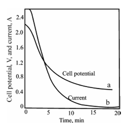
Figure: Change in cell potential (a), and current (b), during a controlled cathode- potential deposition of copper. The cathode is maintained at - 0.36 V versus SCE throughout the experiment.
Above figure describes the changes within cell potential and current during a controlled cathode potential electrolysis of copper. An applied cell potential has to decrease incessantly throughout the electrolysis. That decrease, in turn, diminishes the current. Completion of the electrolysis will be denoting through the approach of the current to zero. This method demands constant attention during operation. Commonly a few provision is made for automatic control.