DC Motor Connections:
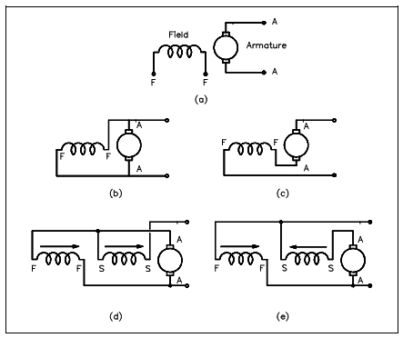
Below Figure displays schematically the various methods of connecting the field and armature circuits within a DC motor. Here the circular symbol represents the armature circuit and squares at the side of the circle represent the brush commutator system. The direction of the arrows denotes the direction of the magnetic fields.

Figure: DC Motor Connections
1. Figure a display and externally-excited DC motor. This kind of DC motor is constructed like that the field is not linked to the armature. This kind of DC motor is not generally used.
2. In another figure b display a shunt DC motor. The motor is known as a "shunt" motor because the field is in parallel or "shunts" the armature.
3. Figure c shows a series DC motor. Motor field windings for a series motor are in series along with the armature.
4. Figures d and e display a compounded DC motor. Compounded DC motor is constructed so in which it holds both a shunt and a series field. Figure d is known as "cumulatively-compounded" DC motor since the shunt and series fields are aiding one another. Figure e is known as a "differentially-compounded" DC motor since the shunt and series field oppose one another.