Turning Moment Diagram of a Single Cylinder Double Acting:
Steam Engine
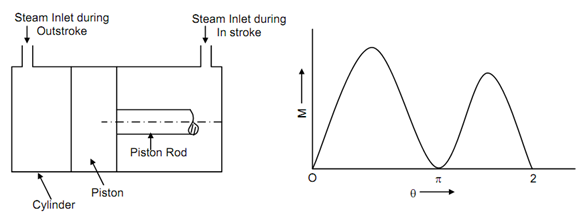
The piston and cylinder arrangement of the steam engine is illustrated in Figure (a) and turning moment diagram is illustrated in Figure (b).
(a) (b)
Throughout out stroke the area over which steam pressure applied is more as compared to in stroke where some area is taken by the piston rod. Due to the difference in the obtainable areas there is difference in the maximum turning moments in the two strokes. Steam pressure is closely constant and variation in the turning moment is because of the value of O2D and inertia force of the reciprocating masses. By compared to the single cylinder 4-stroke engine, in turning moment the variation is less in case of double functioning steam engine.