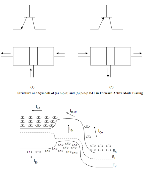
n-p-n and p-n-p BJT:
A bipolar junction transistor (BJT) is a type of transistor. This is a three-terminal device constructed of doped semiconductor material and can be used in amplifying or switching applications. Bipolar transistors are named so because their operation involves electrons and holes both. Although a small part of the base-the majority carriers carry emitter current, minority carriers in the base carry the main current, and so BJTs are classified as
'minority-carrier' devices. A BJT is formed of two p-n junctions as depicted in Figure. They may either one of the transistor configurations : n-p-n (Figure 6.7(a)) or p-n-p (Figure (b)). Note down the direction of current is out of the BJT for n-p-n BJT while it is into the transistor for p-n-p transistor and also the biasing is different for the two BJTs as depicted by (+) and (-) signs in Figure. First point to be noted down is that one of the p-n junction is forward biased, that is called emitter-base junction and the other p-n junction, is reverse biased also termed as collector-base junction, this region of transistor operation is termed as active forward mode. There are four possible modes of operation for transistor. Our concern shall be only for forward active mode. The three terminals of the BJT are called as Base, Emitter and Collector as shown in Figure. Let us understand the operation of a n-p-n transistor first. The operation principle for n-p-n transistor and p-n-p transistor are the same if we change the electrons to hole and change the biasing voltage signs accordingly as illustrated in Figure

Figure: Band Diagram and Carrier Fluxes in BJT
Now, let us draw the band-diagram for this device. Figure is very significant because it illustrates all of the important features in the operation of transistor. As the base-emitter junction is forward biased, electrons shall go from the (n-type) emitter into the base. Similarly, some holes from the base shall be injected into the emitter.