Common-Emitter Amplifier:
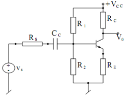
An exemplary common-emitter configuration is illustrated in Figure

Figure: An Exemplary Common-emitter Amplifier
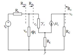
For analyzing this circuit, we suppress the DC voltage (by setting Vcc = 0) and replace the transistor by its small signal AC equivalent circuit in terms of rπ and a current source β ib, supposing r0 → ∞, such an equivalent circuit is shown in Figure. The small signal voltage gain Av, of this amplifier may be found as follows :
The loop equation of the base-emitter loop gives :
Vin = ib rπ + (ib + β ib ) RE
so that we may find
Rib = V in / ib = rπ + (1 + β) RE
The input resistance to the amplifier is, thus, specified by
Ri = R1 || R2 || Rib
Also,
Vin = (R i / Ri + Rs) Vs
and
V0 =- (βib ) Rc

Figure: AC Small Signal Equivalent Circuit of the Common-emitter Amplifier
Combining the above, we get
A v = V0 / V in =- β Rc / [r π + (1 + β) RE]( Ri / Ri + RS )
From the above, we see that if Ri >> Rs and (1 + β) RE >> rπ then
AV ≅ - β Rc/(1 + β) RE = - RC/ RE , for large β.
Furthermore, if RE = 0 and RC >> RS
Av ≅ (β/ r π) RC ≅ - gm Rc
Thus , It is seen that gain is negative which means that input and output of the amplifier are 180o out of place.