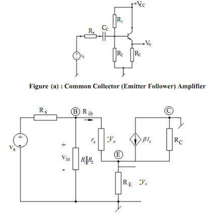
Common-collector (Emitter Follower) Amplifier:
The basic emitter follower arrangement is illustrated in Figure (a), while its small signal ac equivalent circuit is illustrated in Figure (b).

Figure (b) : Small Signal Equivalent of Common Collector Amplifier
From the circuit, we see that I0 = (1 + β) ib so that the output voltage V0 may be written as
V0 = (1 + β) ib (r0 // RE )
The loop equation of the base-emitter loop is
Vin = ib [rπ + (1 + β) (r0 // RE )
from where we get :
Rib = Vin/ ib= rπ + (1 + β) (r0 // RE )
Furthermore,
Vin = (Ri / Ri + Rs)Vs where Ri = R1 // R2 // Rib
From the above equations, at last we find
A = V0 / V s ( (1 + β) [r0 // RE ] / rπ + (1 + β) (ro // RE ))(Ri/ Ri + Rs )
Therefore, it is seen that gain is positive which means that output and input are in same phase.
Also, if (1 + β) (r0 // RE) >> rπ and Ri >> Rs
Av ≅ 1 (In practice, it is, though always slightly less than unity). The small signal output resistance of the circuit is specified by
R0 = ( rπ + (R1 || R2 || R3 ) /(1 + β))|| RE|| r0
From the equivalent circuit, it follows that for Vs = 0 (or Vπ = 0), the small signal resistance looking into the output terminal shall be equal to Rc, Thus,
R0 = RC