Analysis of the BJT DC Bias Conditions:
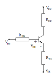
A typical DC bias circuit for biasing the transistor to behaves as an amplifier may be usually simplified by invoking Thevenin's theorem. Therefore, looking out of the 3 terminals of the BJT, the Thevenin's equivalent as illustrated in the circuit in Figure is easily conceivable.

Figure: Basic Transistor Bias Circuit
To analyze such an equivalent circuit, we write a loop equation for the base-emitter loop.
VBB - VEE = I B RBB +VBE + I E REE
Then by using the relation IC = β IB =α IE, we may express IB and IE as functions of the
current IC , as follows :
V BB - V EE = IC / β R BB +V BE + (IC / α )REE
We can then solve for IC.
IC = VBB - VEE - VBE / RBB (IC / β) + ( IC/ α ) REE
An "educated guess" of the value of VBE should be made to evaluate this. Typical values are 0.7V for IC transistors, 0.6-0.65 V for low-power discrete transistors, and 0.5-0.6 V for higher-power discrete transistors.
At last, we may check whether or not the transistor is in active mode. For the active mode, we must check that VCB > 0, which may be done as follows :
VCB = VC - VB = (VCC - IC RCC ) - (VBB - I B RBB )
or = (VCC - IC RCC ) - (VEE + I E REE + VBE )