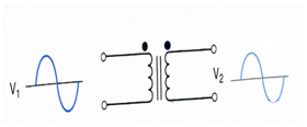
Tranformer Input/Output Phase Relationship
There are two dots in the schematic symbol: one on the top side of the primary winding and the other on top of secondary winding. In this case we will be do working through a transformer which does not generates any phase difference among the input & output.

There are two dots in the schematic symbol: one on the top side of the primary winding and one on the bottom side of the secondary winding.
We are working along a transformer whose output voltage is 180o out of phase along its input voltage as indicated in diagram.
