Negative Half Wave Rectifiers

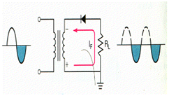
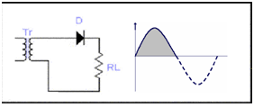
Diagram shows a half wave rectifier along diode direction is reversed. In this circuit the diode conduct on the negative half cycle of the input, &
VL = V2.
For the positive half cycle of the input diode will be in reversed biases and
VD = V2.
As a result positive half cycle of the input is removed. The operating principle of the negative half wave rectifier is similar as the positive half wave rectifiers. Only difference is the polarity of the output will be reversed in this case.
General Rules
(1) While the diode points out towards the load (RL), the output from the rectifier will be positive.
The point built so far is summarized in the diagram below.

(2) While the diode points toward the transformer, the output from the rectifier shall be negative.
The point made so far is shortened in the diagram below.