Peak Inverse Voltage
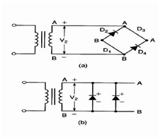
By the ideal diode model, the PIV of each of diode in the bridge rectifier is equivalent to V2.This is the similar voltage which was applied to the diode in the full-wave centre-tapped rectifier. Following diagram helps us to demonstrate this point. In diagram a below, two things have been done:

(A) The conducting diodes (D1 & D3 ) have been replaced by straight wires. Supposing that the diode is ideal they shall have the similar resistance as wire; so replacement is valid.
(B) The positive side of the secondary has been labelled as A & the negative side has been labelled as B.
Linking the common A point with a straight line & doing the similar with B points provides us the circuit indicated in the diagram b. With the correspondent circuit, you might see that two reverse biased diodes & secondary winding of the transformer are all in parallel. As parallel voltages are equivalent, the PIV across each of diode is equivalent to V2.The similar situation will present for D1 & D3 while they are reverse-biased.