Basic Circuit Operation
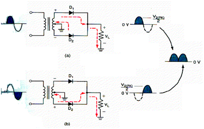
Diagram shows the operation of the full wave rectifier at the time of one complete cycle of the input signal. At the time of the positive half cycle of the input D1 is forward biased .By using ideal operating characteristics of the diode VL can be determined as

While the polarity of the input reverses, D2 is forward biased, & D1 is reverse biased. The direction of the current via the load will not alter even if the polarity of the transformer secondary will changed. Therefore another positive half cycle is generated across the load.