Transmission-line types:
Any transmission line which has a characteristic impedance, or Zo, that depends on line construction. This is sometimes used to construct impedance transformers out of coaxial or parallel wire line.
Transmission line transformers are made from quarter wave sections. The formula for the length of a quarter-wave section can be given by
Lft =246v/fo
here Lft is the length of section in feet, v is velocity factor expressed as fraction, and fo is the frequency of operation is in megahertz. If the length Lm is in meters, then we can say that:
Lm =75v/fo
What happens to the pure resistive impedance at one end of such type of a line? What will be seen at the opposite end of it?
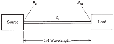
Suppose a quarter wave section of line, with the characteristic impedance Zo, be terminated in the purely resistive impedance Rout. Then input impedance is a pure resistance Rin, and we obtain the following relationship:

This is shown in the Figure given below. This formula can be broken down to solve for Rin in the terms of Rout , or vice versa:

These relationships hold at frequency, fo, for which line is 1/4 wavelength long. Neglecting line losses, these relationships will hold at the odd harmonics of fo, which menas, at 3fo, 5fo, 7fo, and so on. At the other frequencies, the line will not behave as a transformer, but instead, will behave in complicated ways which are beyond the scope of this discussion.
Quarter-wave transformers are mostly used in antenna systems, especially at higher frequencies, where dimensions of them become practical.
Problem:
The antenna has a purely resistive impedance of 100 ohms. It is connected to a 1/4-wave section of 75 ohms coaxial cable. What will be impedance at input end of the section?
By using the above formula:

Figure--A quarter-wave matching section of transmission line.
