Design Steps Part-2
Step 4. Isolate the transform center through specifying outgoing and incoming flow boundaries.By the preceding section incoming flow was define as a path in which information is converted from external to internal form outgoing flow converts from internal to external form. The Incoming and outgoing flow boundaries are open to interpretation. Which are different designers may select slightly different points in the flow as boundary locations.In reality, alternative design solutions can be derived through varying the placement of flow boundaries.While care should be taken when boundaries are selected a variance of one bubble along a flow path will commonly have little impact on the last program structure.
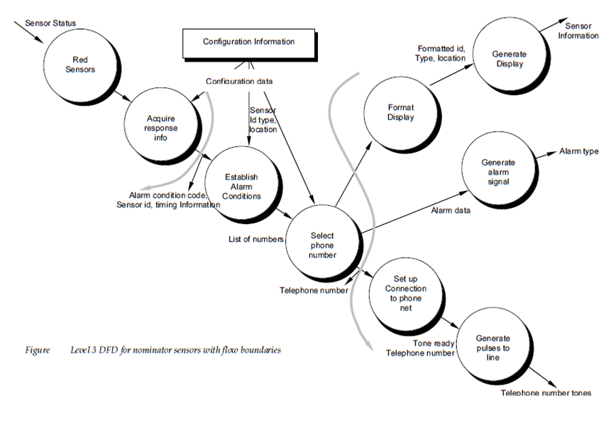
Flow boundaries for the example are demonstrate as shaded curves running vertically by the flow. The transforms bubbles which comprise the transform center lie within the 2 shaded boundaries which run from top to bottom in the shown figure. An argument can be made to readjust a boundary example for an incoming flow boundary separating read acquire and sensors response info could be proposed. Emphasis in this design step should be on selecting reasonable boundaries rather than lengthy iteration on placement of divisions.
Step 5. Perform 1st level factoring. The Program structure represents a top down distribution of control. The Factoring results in a program structure in which top-level modules perform low- level and decision making modules perform computational, most input and output work. The Middle-level modules perform some control and do moderate amounts of work.
When transform flow is encountered a Data Flow Diagram is mapped to an exact structure which gives control for transform, incoming and outgoing information processing. This 1st level factoring for the monitor sensors subsystem is main controller which is called monitor sensors executive resides at the top of the program structure, serves to coordinate the following subordinate control functions;
An incoming information processing controller is called sensor input controller, coordinated receipt of all incoming data;A transformation flow controller which is called alarm conditions controller supervises all operations on data in internalized form example for a module which invokes several data transformation procedures;An outgoing information processing controller which is called alarm output controller and coordinated production of output data.
While a 3 pronged structure is implied through figure complex flows in huge systems may dictate 2 or more control modules for each of the generic control functions define above. The number of modules at the 1st level should be limited to the minimum which can accomplish control functions and yet maintain cohesion characteristics and good coupling.
Step 6. Perform 2nd level factoring. 2nd level factoring is accomplished through mapping individual transforms bubbles of a Data Flow Diagram into appropriate modules within the program structure. Starting at the transform center boundary and moving outward beside incoming and then outgoing paths transforms are mapped into subordinate stages of the software structure. The common approach to 2nd level factoring for the Safe Home data flow is described in figure 20.8.
While figure demonstrates a one-to-one mapping among Data Flow Diagram transforms and software modules various mappings frequently occur. 2 or even 3 bubbles can be represented and combined as one module recalling potential problems with cohesion or a single bubble may be expanded to 2 or more modules. By Practical considerations and measures of design excellence dictate the outcome of 2nd level factoring. A Review and refinement may lead to changes in this structure but is can serve as 1st design iteration.
2nd level factoring for incoming flow follows in the similar manner. Factoring is again accomplished through moving outward from the transform center boundary on the incoming flow side. Transform center of monitor sensors subsystem software is mapped somewhat in a different way. Each and every of the data calculation or conversion transforms of the transform portion of the Data Flow Diagram is mapped into a module subordinate to the transform controller. A finished 1st iteration program structure is described in figure .
The modules mapped in the manner define above and represent an initial design of program structure. While modules are named in a manner which implies function, a short processing narrative adapted from the PSPEC established during analysis modeling should be written for each.