Modeling of a Geared System into a System of Rotors:
Connected by a Shaft of Uniform Diameter
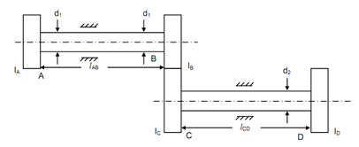
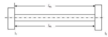
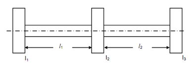
A rotor system with a gear unit is illustrated in Figure 16(i). If inertia of gear unit is neglected, it may be modeled in two rotor system as illustrated in Figure 16(ii) or else it is modeled into a three rotor system as illustrated in Figure 16(c).

(i)

(ii)

(iii)
Let ωAB = Speed of shaft AB, and
ωCD = Speed of shaft CD.
ωAB / ωCD = tC / tB = pcd of C / pcd of B = C
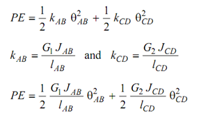
The potential energy and kinetic energy of the geared system are specified by following
 . . . (53)
 . . . (54)
As
ωAB /ωCD = C = θ AB /θCD
∴ ωCD =ω AB /C and θ CD = θ AB /C
 -------------- (55)
 --------------- (56)
KE and PE for system illustrated in Figure 16(ii).
KE = (I /2 ) I1 ω2 + (I /2) I2ω2 ----------- (15.58)
PE = ( 1 /2 ) (GJ / Ieq ) θ2 --------------(57)
If inertia of the gears is negligible the terms with IB and IC can neglected in Equation (55). By equating KE given by Equation (55) and Equation (57).
I1 = I A and I2 = I B/ C2 -------------- (59)
By comparing PE specified by Equation (56) and (57)
leq. = lAB + (G1/ G2 )(d1/d2)4 lCD -----------------(60)
If the inertia of the gears is not negligible. By comparing KE given in Equation (55) with KE of three rotor system model specified in Equation (61)
KE = (1/2) I1 ω2 + (1/2) I2 ω2+ (1/2) I3 ω2 ---------- (61)
I1 = I A, I2 = I B + (IC /C 2) and I3 = I D / C 2 --------------(62)
By comparing potential energies with that of three rotor model given in Equation (63)
 ----------- (63)
l1 = lAB and l2 = (G1 /G2)(d1/d4)4 C 2 lCD