Thin Walled Non-circular Section Shafts:
In the preceding section we saw that the determination of stresses in non-circular members generally requires the use of advanced mathematical methods. In the case of thin walled hollow non-circular shafts, however, a good approximation of the distribution of stresses in the shaft can be obtained by a single computation.
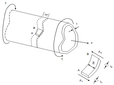
Let a hollow cylindrical member of non-circular subjected to a torsional loading illustrated in Figure.

Figure
While the thickness t of the wall may very within a transverse section, we shall assume that it remains small compared to the other dimensions of the member. Let us assume a small portion AB bounded by two transverse planes Δx apart, and by two longitudinal planes. As the portion of AB is in equilibrium, the addition of the forces exerted on it in the longitudinal x direction as well as that in transverse direction must be zero. The forces exerted on the small element along the length are shearing forces FA and FB.
∴∑ Fx = 0 i.e. FA - FB = 0 --------(i)
FA may be expressed as the product of the longitudinal shearing stress τA on the small face at A and of the area tA. Δx of that face.
Similarly,
FA = τ A (t A Δ x) ----------- (ii)
FB = τB (tB Δ x) ------------(iii)
On putting Eqs. (ii) and (iii) in Eq. (i), we obtain
τ A (t A Δ x) - τB (tB Δ x) = 0
or, τ A t A = τB t A
Eq. expresses that the product τ t of the longitudinal shearing stress and the wall thickness is constant throughout the member. Mentioning this product through q.
q =τ t = constant
The quantity 'q' is referred to as shear flow in the wall of the hollow shaft.