Tool Presetting
Since the generation of actual geometry is taken care of by the CNC part program, which is in essence the coordinates through which the cutting tool tip moves, it is significant to know the actual dimensions of the tool when it is placed in the spindle. The relationship of the tool along reference to the tool holding mechanism requires a special attention during CNC machining process.
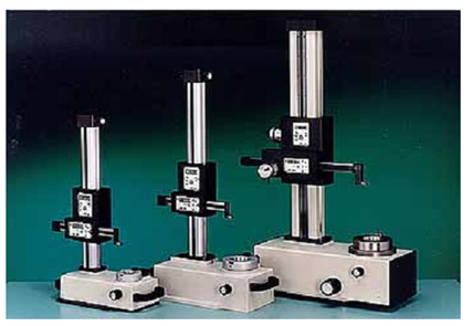
The actual point to be programmed in a CNC part program is the tip of the tool whereas the axes will be moving with respect to a known point in the spindle, e.g. the centre of the spindle in case of machining centres. Therefore it becomes necessary to know precisely the deviation of the tool tip from the gauge point on the spindle. Therefore the tool setting equipment is generally used. A simple mechanical type tool setting device is shown in Figure 12.

Figure 12 : Typical Tool Setting System Useful for Machining Centre Tooling
In this system, which is very similar to a two axis height gauge, the base is provided with the exact taper as used in the actual machine tool. Therefore the assembled tool is placed in the spindle taper. The measurement is done through the help of a probe head, which can move in two axes along the column and perpendicular to it as shown in Figure 12. The probe can measure the diameter as well as the length of the tool. The display is shown digitally so that there is no error in measurement. Also some of the systems are provided with a serial port for sending the measured values directly into any tool management system or a personal computer for the purpose of generating the tool offset values. A variation in these presetting systems is that they are provided with an optical projector element for the accurate identification of the tool tip.