Geometric Tolerancing
The concept of conventional method of dimensioning merely provides information concerning surface and size condition.
Conventional tolerancing methods have three following main short comings :
(1) They are incapable of controlling all of the aspects of the shape of a part. In addition to the control of position, size and angle, control is also needed for the form (shape) of features, such like flatness, straightness parallelism or angularity of specific portions of the part.
(2) Conventional tolerancing does not utilize the concept of datum that is an significant concept to manufacture and inspect the part. It does not explicitly specify datums or their precedence. Usually Datums are implied from the way the part drawings are dimensioned.
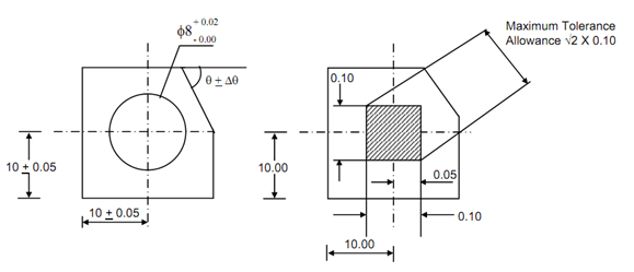
(3) Extending the conventional tolerancing methods to control locations (that means two or three dimensional control) explained in rectangular candidates or angular dimensions introduce undesirable result because of the variation in the size of the tolerance zone. Assume, for instance, the control of the location of the centre of the hole illustrated in Figure 8(a). Specifying a tolerance of

Figure 8 : Positional Control of the Center of a Hole
+ 0.05 mm on the coordinates of the center (10.00, 10.00) the 0.10 × 0.10 in square tolerance zone illustrated in Figure 8(b) while the results in designer may think that he/she is controlling the location of the center of the 10.00 mm hole in a 0.10 mm boundary, the center could in fact vary across the diagonal of the square tolerance zone, yielding a maximum tolerance of 0.14 mm rather than 0.10 mm. Therefore, conventional tolerancing gives more freedom in the diagonal directions and might unnecessarily constrain errors in the horizontal (or radial) and vertical (angular) directions.