Proof of Thevenin Theorem
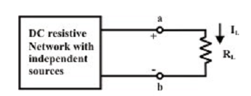
The fundamental concept of this theorem and its proof are depend on the principle of superposition theorem. Let us consider a linear system as shown in figure below.

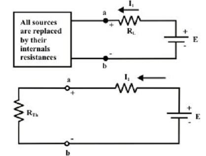
It is supposed that the dc resistive network is excited by the independent current and voltage sources. In common, there will be certain potential difference (VOC = VTH) among the terminals ‘a’ & ‘b’ whenever the load resistance RL is disconnected from the terminals. The figure below shows an additional voltage source (i.e., ideal) is connected in series with the load resistance RL in such a manner (i.e., polarity of external voltage source E in opponent the open-circuit voltage VOC across ‘a’ & ‘b’ terminals) and hence the combined effect of all internal and external sources answers zero current via the load resistance RL.

According to the principle of superposition, the zero current flowing via RL can be considered as an algebraic sum (i.e., consider the direction of currents via RL) of (a) current via RL due to the external source E only whereas all other internal sources are substituted by their internal resistances (i.e., all voltage sources are short-circuited and all the current sources are open circuited), and (b) current via RL due to the collective effect of all internal sources whereas the external source E is shorted with a wire. For the primary situation, suppose the current I1 [= E/ (RTH + RL)] is flowing via RL from right to left direction (←) as shown in figure below.

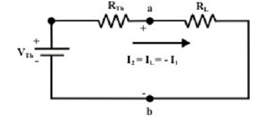
For the second situation, the current I2 (due to collective effect of all the internal sources only) is flowing via RL with similar magnitude of I1 though in reverse direction (i.e., from left to right). Note that the resulting current I via the resistor RL is zero due to the combination of internal and external sources. This situation will occur provided the voltage (Vab) across the ‘a’ & ‘b’ terminals is exactly similar (with identical polarity) as that of external voltage E and this further entails that the voltage across Vab is nothing though an open-circuit voltage (VTh) whereas the load resistance RL is disconnected from the terminals ‘a’ & ‘b’. With the logics as explained above, one can find the current expression, I2 [= VTh/ (RTh + RL)] for the original circuit whenever the external source is short-circuited with a wire. In another words, the original circuit shown above can be substituted by an equivalent circuit which delivers the similar quantity of current IL via RL. The figure shown below shows the equivalent Thevenin circuit of the original network.
