Torsional Displacements:
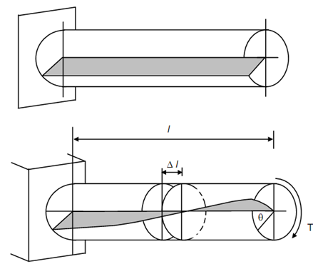
Figure (a) shows a circular shaft rigidly held at one end A. Radial plane within the shaft is shown shaded. Figure shows the same shaft after a torque T has been applied at the free end. As a result the shaded plane of Figure (a) will twist as shown in Figure (b). However, according to assumption made earlier any cross-section of the shaft remains plane after torque T has been applied. So the two cross-sections at a distance of Δ l in Figure are plane. This supposition is verified through experiment. A small portion of length Δ l is isolated in Figure. The torque at each end is T. The plane OACD warps into plane OA′CD. Point A moves to A′, and point B on a circle of radius r moves to B′, while remaining on the same circle. Δ θ is the angle moved through radius OA (unloaded position) to OA′ (load position). Δ θ is the angle of twist. The line AC on the surface of the shaft in unloaded condition, now occupies the position A′C after loading. The angle between AC and A′C is γ at point C. γ is apparently the angle of distortion of the shaft, therefore, shearing strain in length Δ l. One can easily imagine that the angle of distortion (γ) will be maximum on the surface and will reduce linearly from C to D. It will eventually become zero at the point D, the centre of the cross-section
Arc AA′ =γ Δ l = Δ θ d /2 -----------(1)
where, Radius, OA = d /2, and
d = shaft diameter.
Arc BB′ = γr Δ l = Δ θ . r -------------- (2)
where γr is the angle of distortion or shearing strain at radius r.
(a)