Yield Strength
A material placed into a machine or structure to function as a load carrying member is never permitted to deform plastically. Hence, designers often need to characterize a material via its elastic strength. There are two categories of strength, can be recognized from illustration. They are practical and "ideal" elastic strengths. Useful elastic strengths are as: "elastic limit" and "proportional limit".
Proportional limit or a material is a stress upto that material has linear relationship in between strain and stress.
A material's elastic limit is the stress upto such a material behaves elastically. The sense of elastic or elasticity behaviour has already been illustrated.
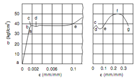
In following figure stress level subsequent to point a is the proportional limit and that consequent to point b is the elastic limit. All the ideal strength values are seldom employed in actual characterization of material since of difficulties in their determination. Hence, practical elastic strength values are determined and explained.

Figure: (a) along with Strain Scale Expanded Showing Yield Deformation and
(b) Along with Strain Scale Shortened to represents Ultimate and Fracture Point along with Yield Point
The yielding behaviour of structural and mild steel is shown in above figure (a) on an expanded scale of strain or abscissa axis. Such figure emphasizes the fact that whole deformation during yielding is concerning ten times the deformation upto elastic limit. The yielding is represented to end at point e beyond that the plastic deformation continues like is shown in above figure (b). The point c is the higher yield point and d the lower yield point. The difference in between lower and upper yield point exists since movement of the ends of the specimen as generated via two machine cross-heads, doesn't proceed as quick as the yield deformation of material. Such fact might be confirmed by permitting the loading cross-head to move very fast that is the state of the impact loading. In a state simply one yield point that is the upper yield point such will exist. For materials that show lower and upper yield points, the latter is considered as the "yield strength" since it is less affected by variables.
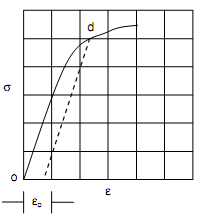
Most ductile materials do not yield and show curve of Figure of Stress-strain Diagram for Ductile Materials (a) or as in Figure of Determination of Proof Stress. For such materials the end of elastic behaviour is explained as attaining a specific plastic strain. The determination method of this strength value is to measure a specific offset strain from origin like in Figure of Determination of Proof Stress represented by oA. a line parallel to elastic strength line part, from point A is represented to meet the curve at d. the stress corresponding to point d is explained as the "proof strength" or "yielding strength" of the material. The offset strain values have been standardized for assorted materials. The yield strength determined via the offset method is always explained as yield strength for an offset. Table no.1 illustrates the values of offset strains commonly employed.

Figure: Determination of Proof Stress
Table no.1: Commonly employed Offset Values or A.S.T.M.E6-35T
|
Material
|
Types of Stress
|
Percent
|
Equivalent Strain
|
|
Aluminium alloys
|
Tension and Compression
|
0.20
|
0.0020
|
|
Brass or bronze
|
Tension and Compression
|
0.35
|
0.0035
|
|
Concrete
|
Compression
|
0.02
|
0.0002
|
|
Cast Iron
|
Tension
|
0.05
|
0.0005
|
|
Steel
|
Tension and Compression
|
0.20
|
0.0020
|
|
Wood
|
Compression
|
0.05
|
0.0005
|