Universal Testing Machine
Mechanical Determination and Their Properties
Common testing machine is to be illustrious from a special reasons machine in the means that such a machine is employed for performing various tests. Tests that are presented in a universal or common testing machine are tension, transverse shear, bending, compression and hardness. Conversely, a special machine as like torsion testing machine or compression machine can be employed only for specific test as shown by name.
Two categories of universal testing machines are in common employs. One is mechanical type operated by gear and screw as represented in following figure and the other is hydraulic universal testing machine as shown in following next figure. Both such machines are basic in nature. The screw type category varies in capacity and size over wide range of a few newtons to a few tones. Hydraulic machines are commonly of high capacity. Such machines have limited speeds of movement of cross-heads hence loads applied are inside the definition of static. The strains rates greater than 10-6 mm/mm.s are normally not available upon universal testing machine. Modern computer operated machines currently make broad range of strain rates obtainable or available and they can be even employed for cycling stresses. MTS and Instron machines are demonstrated.
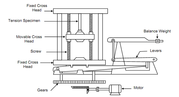
Figure: Screw-Gear Type Universal Testing Machine
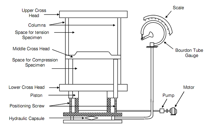
Figure: Schematic of Hydraulic Universal Testing Machine
Whatever by the category of machine common features keeps same, a universal machine applies axial load that can serves as tension, compression, shear or bending load on the test piece or specimen depending upon positioning of the test piece. The application of load is effected via relative movement among two cross-heads. Universally machines have two cross-heads rigidly linked along with each other and a third cross-head is positioned among them. All machines have proper specimen supporting and holding devices to apply desired type of load upon the test piece. The load applied upon the test piece has to be balanced and measured and such all machines should have this device.
Figure of Screw-Gear Type Universal Testing Machine, shows essential features of a mechanical type of universal testing machine. The lower and upper cross-heads are rigidly linked with middle cross-head can be moved down via a screw and gear arrangement driven via an electric motor. Whilst moving down the middle or movable cross-head could apply a tension load on a test piece gripped between the upper cross-head and moving cross-head. Otherwise, the middle cross-head can apply a compressive load upon a test piece placed on lower cross-head. The fixed cross- heads are holed over a compound lever system at that end a poise or balance weight can be shifted to attain balance of the lever and hence measure the applied force. The balance weight is frequently replaced via a swinging pendulum such rotation is transmitted to an indicator throughout gear train for direct denoted of load.
In a hydraulic universal testing machine in figure of Schematic of Hydraulic Universal Testing Machine, the rigid frame containing lower and upper cross-head is attached to an accurately over piston that exactly matches along with the hydraulic cylinder. The middle cross-head, such position is adjustable keeps stationary while the load is applied upon the specimen. An electric motor rotates a hydraulic pump such forces the oil in the cylinder whereby the rigid assembly of lower and upper cross-head is lifted up. Throughout this movement a tensile load will serves upon the specimen held between middle and upper cross-head and a compressive force will react upon a specimen placed upon the lower cross-head. The hydraulic pressure upon the bottom of the hydraulic cylinder is transmitted to a hydraulic capsule that is linked to a Bourdon tube gauge such can be calibrated to read the force directly. The middle cross-head can be moved down or up via separate positioning screws and during its positioning movement the hydraulic pump is not operated.
To plot the load displacement curves, all types of machine often incorporate the mechanical graphical devices. Modern machines displacement gauges and incorporate load cell whose electrical signals respectively proportional to displacement and load can be plotted automatically on X-Y plotter while the test is proceeding.