Bridge Circuit Construction:
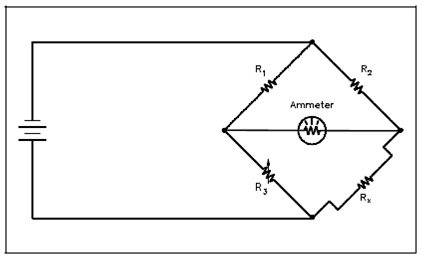
Above Figure displays a basic bridge circuit that consists of three knew resistances, R1, R2, and R3 (variable), an unknown variable resistor RX (RTD), a source of voltage, and a sensitive ammeter.

Figure: Bridge Circuit
Resistors R1 and R2 are the ratio arms of the bridge. That ratio the two variable resistances for current flow through the ammeter. R3 is a variable resistor called as the standard arm that is adjusted to match the unknown resistor. The sensing ammeter visually displays the current that is flowing through the bridge circuit. Analysis of the circuit displays in which while R3 is adjusted so that the ammeter reads zero current and the resistance of both arms of the bridge circuit is the same. The Given Equation 1-1 shows the relationship of the resistance between the two arms of the bridge.
R1/R3 = R2/Rx (1-1)
Because the values of R1, R2, and R3 are known values, the only unkown is Rx. A value of Rx could be calulated for the bridge during an ammeter zero current condition. Getting this resistance value provides a baseline point for calibration of the instrument attached to the bridge circuit. The unknown resistance Rx, that is provided through Equation 1-2.
Rx = R2R3/R1 (1-2)