Pearlite
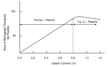
The tensile strength of pure iron as 0.00% C is around 250 N/mm2 that increases to about 850 N/mm2 at a carbon percentage of 0.8. At extremely low carbon percentage the whole metal is made up of ferrite grains such are ductile and soft. Along with increasing carbon percentage more and extra material is made up of pearlite, a substance such appears to comprise colour of mother-of-pearl, thus the name. At 0.4% carbon pearlite inhabits almost half the region viewed via microscope. At such level of carbon the tensile strength is about 540 N/mm2. At 0.8% carbon approximately total area consists of pearlite along with strength of 850 N/mm2.
Pearlite examination at higher magnification as X 1500 reveals, it has a laminated structure. It is a composite consisting of cementite and ferrite of alternate layers.
Cementite offers the strength whilst ferrite retains steel ductility. At carbon content above 0.8% the quantity of Fe3C begins to raises and steel begins to lose its ductility. Figure of Relationship between Pearlite % and Carbon Content, represents relationship between carbon and pearlite content. Outside the area of demonstration of Relationship in between Pearlite % and Carbon Content, inside the range of carbon in between 0.9 percent and 1.2 percent pearlite structure still exists, however grains are contained via cementite network. Such cementite networks not being parts of grains are concerned to as free cementite and are the reasons of brittleness in steel. Generally the strength of steel does not increase because of the presence of free cementite, afterward it may reduce underneath the level of 0.8% carbon steel.
Because pearlite is a significant constituent of steel is control becomes significant if properties of steel are to be under controlled. This will be worthwhile to distinguish how it is formed. Along with reference to Figure of Cooling Curve of Pure Iron with Steady Rate of Heat Loss, three forms of iron were represented. These forms are concerned to as allotropic forms of iron and at every transformation a thermal arrest is experienced.

Figure: Relationship between Pearlite % and Carbon Content
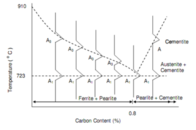
Throughout the cooling of pure iron the conversions or transformation from g-iron (fcc) to a-iron (bcc) happens at a usual temperature of 910oC. Though, carbon is added to the iron to form steel this transformation obtains place over temperature's range. The limits of such range are termed as the critical points and the higher temperature at that, transformation starts during cooling is implicated A3. The lower point is demonstrated as A1. This was stated in Section of Harden-ability Of Steel, that the lower temperature A1 keeps constant at 723oC irrespective of the carbon content whilst the higher temperature A3 slowly reduces like carbon percentage increases as in figure of Iron-Carbon Phase Diagram. At a carbon percentage of 0.8, A3 and A1 are equivalent to 723oC. If carbon percentage additionally increases, A3 also increased. The equilibrium figure will be acquired if A3 and A1 temperatures are plotted against carbon percentage as demonstrated in Figure of Critical Points for Carbon Steel. The detailed phase diagram has previously been represented in Figure of Iron-Carbon Phase Diagram. This demonstration shows how g-iron that is austenite is transformed in pearlite.

Figure: Critical Points for Carbon Steel
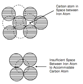
It may be noticed that carbon solubility is not same in austenite than in ferrite. The fcc as g-iron can hold as more as 1.7% carbon in solution at 1130oC. Inside the range of carbon beneath discussion the structure is entirely austenite at such temperature and all the carbon is in solution. Then the carbon is dissolved interstitially or can say a carbon atom does not replace an iron atom to form part of the cube as in figure (a) of Interstitial Solution of Carbon. While the lattice is arranged to comprise a bcc structure the carbon atoms is ejected from its site as in figure (b) of Interstitial Solution of Carbon, since space is insufficient. It is the reaction that takes place at A3.

Figure: Interstitial Solution of Carbon
The sequence of events in between temperatures A2 and A1 is demonstrated in figure of: Transformation of Austenite in 0.4% C Steel, as Cooling happens from Molten State above A3 Temperature, during that austenite transforms in pearlite. The bcc ferrite grains nucleate on the austenite grain's boundaries. As the temperature fall the ferrites covers more and extra are in austenite grain that decreaes in size. The ferrite's separation from austenite will result in rejection of carbon that will be absorbed with remaining austenite. Hence the continuing austenite gets richer in carbon till the carbon amount reaches 0.8% causing precipitation of layers of cementite in the austenite region. Hence, the austenite transforms into pearlite having of layers of ferrite and cementite. Hence transformation of austenite is same to eutectic reaction but because it arises in the solid state, it is termed eutectoid transformation. Such eutectoid reaction or breaking of solid phase austenite in cementite and ferrite as already illustrated in Section of Special Treatments, takes place at temperature of 723oC that is termed A1. For this purpose pearlite is often concerned also as eutectoid.