Dynamic Force Analysis:
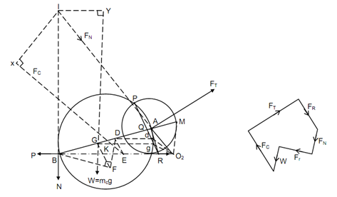
Figure 13(a) illustrates reciprocating engine mechanism O2 AB. Assume:
mp = Mass of reciprocating parts,
mc = Mass of the connecting rod
N = Reaction at the cylinder wall,
Fr = Radial component of the force at the crank pin,
Ft = Tangential component of the force at the crank pin,
P = Net force at the piston along the line of stroke,
Fc = Inertia force on the connecting rod,
ap = Acceleration of the reciprocating mass,
K = Radius of gyration of connecting rod, and
P = Gas force ± mp ap
Weight of connecting rod, W = mc g.
Fig(13)
As acceleration of several points shall be needed, Kleins construction may be drawn and O2AQR shows acceleration diagram. The process for drawing already this has been described earlier.
The connecting rod may be replaced by a dynamically corresponding system. One of the masses may be placed at the small end and the piston of the other mass may be estimated by using the following equation.
 . . . (12)
Here G being the centre of gravity. Point R may be joined along R to represent resultant acceleration of the connecting rod. The horizontal lines (means parallel to the line of stroke O2B) may be drawn from points G & D to find out acceleration of these points. The acceleration of G & D are given by ω2 O2g and ω2 O2d, here ω being angular velocity of the crank. The length scale is similar as that of the configuration diagram.
FC = mc ω2 O2 g
Draw the lines of action of N and Fr so that they meet at point 'I'. From point D draw a line DE parallel to dO2 to meet O2B at E. The resulting inertia force on the connecting rod passes through point E. hence, draw a line from E parallel to gO2 to define line of action of resultant inertia force 'FC' on the connecting rod. The line of action of the weight 'W' might also be extended. Fall perpendiculars from I to the lines of action of FC and W which are I X and I Y. To determine Ft, moment of different forces may be taken and the following equation is obtained.
Ft I A = P × I B + FC × I X + W × I Y . . . (13)
or 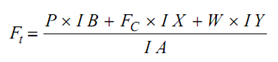 . . . (14)
To determine Fr and N, force polygon can be drawn as illustrated in Figure 13(b) that will give their magnitudes as their directions are already known.