Wilson-Hartnell Governor:
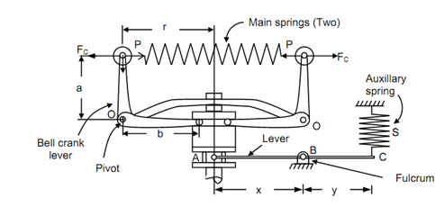
A Wilson-Hartnell governor is illustrated in given Figure. In this, the balls are associated by two springs that are known as main springs. The main springs are symmetrically arranged on either side of the sleeve. The balls are associated to the vertical arms of the two bell-crank levers. The horizontal arms of bell-crank levers hold two rollers at their ends. At the horizontal arm the rollers press against the sleeve. The bell-cranks rotate along the spindle. While speed enhances the ball-radius reduced, the springs exert an inward pull P on the balls and the rollers press against the sleeve that is raised.
An adjustable auxiliary spring (S) is connected to the sleeve by the means of a lever. The lever is pivoted at a fulcrum B. One of the ends of the lever is linked to the auxiliary spring while the other end of the lever fits into the groove in the sleeve. The auxiliary spring tends to remain the sleeve down.

Wilson-Hartnell Governor
Assume m = Mass of each of ball in kg,
M = Mass of sleeve in kg,
W = Weight of sleeve = M × g in N,
P = Tension (or Pull) in the main spring in N,
S = Tension in the auxiliary spring in N,
FC = Centrifugal force of each ball in N,
r = Radius of rotation of balls in m,
s = Stiffness of auxiliary spring in N/m, and
sa = Stiffness of auxiliary spring, in N/m.
The total downward force on the sleeve
= Weight of sleeve + force at lever ending A due to tension S in auxiliary spring (that is at point C)

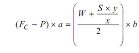
By taking the moments around the point 'O' of the bell-crank lever and neglecting the influence of the pull of gravity on the balls, we get the following

At the minimum speed 'ω1', let

P1 = Tension in main spring, S1 = Tension in auxiliary spring & FC2 , P2 and S2 are equivalent values of centrifugal force, tension in main spring and tension in auxiliary spring equivalent to maximum speed, respectively.
By putting these values in above equation, we have for minimum speed, 'w1'.

Likewise for maximum speed 'ω2', we have the following

By subtracting equation (12.15) from equation (12.16), we have the following

While the radius increases from r1 to r2, the ball springs shall be extended by the amount (d2 - d1) of 2 (r2 - r1) and auxiliary spring shall be extended by the amount  The main spring consists of two springs.
∴ P2 - P1 = Net pull (or tension) in two main springs while radius increases from r1 to r2,
= 2 × Force exerted by each of the main spring,
= 2 × [stiffness of main spring × extension of ball springs],
= 2 × [s × 2 (r2 - r1)], and
= 4 × s × (r2 - r2) = 4s. (r2 - r1).
Likewise, extension in the auxiliary spring may also be estimated. The movement of the sleeve as radius modify r1 to r2
= b/a (r2 - r1 )
∴ Extension in the auxiliary spring

Assume the stiffness of the auxiliary spring be sa.

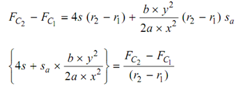
By substituting for (P2 - P1) and (S2 - S1) in equation (12.17)
 . . . (12.18)