Application
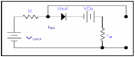
Let the circuit as indicated, for analysis reason, we may split the circuit into two partitions that is ac & dc

DC source with the value of VDD
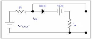
We replace the ac & replace diode along with constant drop model
For dc analysis the Circuit is as

In case of DC we let only DC current ID is passing and no effect of the ideal diode due to this ideal diode is forward biasing and this results in short circuit so
From KVL eq
VDD -IDR - VDo - ID rd = 0
VDD = IDR+ VDo + ID rd ---------------- (i)
In case of DC just DC current ID is passing
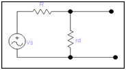
For ac analysis we have to remove DC sources that are the part of the main circuit and also remove the DC source that appear in the earlier effective circuit and we also eliminate the ideal circuit therefore our circuit became as

For analysis of ac
vs = id (R + rd) ------------- (ii)
by joining (i) & (ii)
Total analysis is
VDD + vs =IDR + VDo + ID rd + id (R + rd)
= ID(R + rd) + id (R + rd) +VDo
VDD + vs = (R + rd)( ID + id) + V D0 ------------ (iii)
However
ID + id = iD
So
VDD+ vs = (R + rd)( ID + id) + V D0
Separating the dc & signal quantities on both of the sides of equation (iii)
VDD = IDR + VD0
That is shown by the circuit in the diagram below

And for the signal
vs = id (R + rd)
that is shown by the circuit in the diagram below

but, if we carefully analysis the ac equation circuit, this is nothing more than a voltage divider.
So the diode signal voltage is
Vd = Vs rd/(rd +R)