Op-amp As a Comparator:
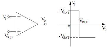
In this section, we shall study how an op-amp may be utilized as a comparator. A comparator is an active circuit element which contain two input terminals and one output terminal. The output voltage exhibits two stable states. The output state based on the relative value of one input voltage compared to the other input voltage. Figure (a) illustrates the circuit diagram of an op-amp utilized as an inverting comparator. The voltage applied to the non- inverting input is the dc reference voltage VREF. The output voltage is given by
v0 = A (VREF - vI )
where A is the voltage gain of the op-amp. For an ideal op-amp, we suppose that A → - ∞. This implies that v0 → ∞ for v1 < VREF and v0 → - ∞ for v1 > VREF. Though, a physical op-amp may not have an infinite output voltage. Let us indicate the maximum voltage of the magnitude of the output voltage by VSAT. We call VSAT the saturation voltage of the op-amp.

(a) (b)
Figure: (a) Inverting Comparator; and (b) Plot of v0 Versus vI.
For an ideal op-amp that exhibits saturation of its output voltage, the output voltage of the inverting comparator circuit in Figure (a) may be written as
v0 = VSAT sgn (VREF - vI )
where sgn (x) is the signum or sign function described by sgn (x) = + 1 for x > 0 and sgn (x) = - 1 for x < 0. The plot of v0 versus vI for the circuit is given in Figure (b).