Force Circle Diagram:
The horizontal cutting force Fc and vertical force Ft might be measured in a machining operation by the utilization of a force dynamometer. The electric strain gauge kind of transducer is utilized in the dynamometer. After Fc and Ft are found out, they might be laid off as in Figure 2 and their resultant is the diameter of the circle. The rake angle a might be laid off, and the forces F & N might then be resolute. The shear plane angle f might be measured approximately from a photomicrograph or by computing tc and tu, or length of chip and equivalent length of unmachined chip .
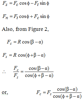
From Figure 2, the following vector Equations. might be written

Merchant represented several forces in a force circle diagram in which tool and reaction forces have been supposed to be acting as concentrated at the tool point rather than their definite points of application along the shear plane and the tool face. The circle has the diameter equivalent to R (or R') passing through tool point.
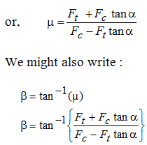
After Fc, Ft, a and fare known, all of the component forces on the chip might be resolute from the geometry. For example, the average stress on the shear plane might be resolute by utilizing force Fs and the area of the shear plane. Another helpful quantity is the coefficient of friction (m) among the chip and tool. By using force circle diagram, it can be illustrated that
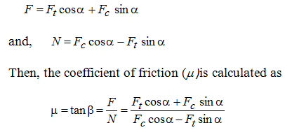
here, b is the friction angle.
From Figure 2, we obtain :
Shear plane area is equivalent to following:
 ------------------ (9)
If t be the shear strength of the work material, afterwards,
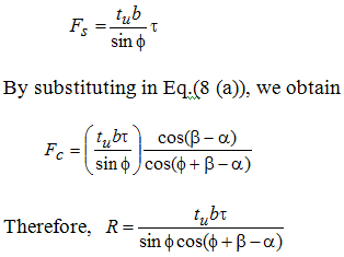
From Fig 2,
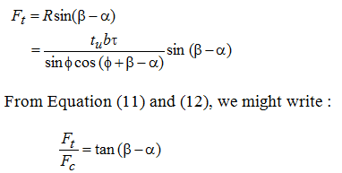
From the above described analysis, in the force circle diagram unknown forces and the value of coefficient of friction might be computed provided Fc, Ft, a, tu and tc are known measured.
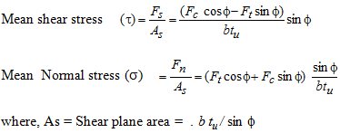
Throughout machining operations, chips are made as a result of plastic deformation. Therefore, chips experience strains and stresses. At shear plane, simultaneously two normal forces act, that means. Fs and Fn. Shear stress (t) might be found as
