Whirling of Shafts:
Throughout whirling of the shaft there are two component rotations are follwing:
(i) Rotation of the disc around its own bent up axis.
(ii) Rotation of the plane marked by 'X' among the bent up axis and bearing centre line around the bearing centre line oo′.
These two rotational speeds might be similar or different. If they are similar then it is known as synchronous whirl or else it is non-synchronous whirl.
At critical speed, shaft vibrates along very big amplitude that might result in the breakdown of the shaft.
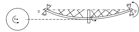
Let a light vertical shaft illustrated in Figure.
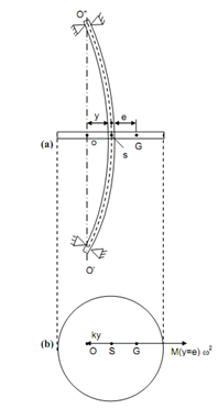
Assume m = mass of the disc,
e = eccentricity of the centre of gravity & disc from the shaft axis centre on the disc 'S'.
k = stiffness of the shaft in lateral direction,
ω = angular speed of the disc around shaft axis, and
y = lateral distance of 'S' from 'O' that is the point of intersection of bearing axis at the disc.
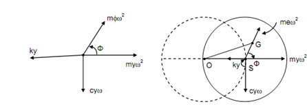
Let us assume first that there is no damping in the system. The several forces acting on the disc are illustrated in Figure 8(ii). hence,
ky = m ( y + e) ω2
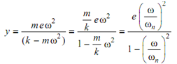
While ω = ωn, that is at resonance, the deflection 'y' becomes infinite. Therefore, is the critical speed of the shaft. The shaft must operate in the neighbourhood of this speed or else shaft might breakdown. While ω < ωn, the deflection is positive i.e. the layout of deflection y is in the similar sense as e and this layout is illustrated in Figure 8(ii). In this case phase angle is zero. While ω > ωn, deflection 'y' is negative. It means that the layout of 'y' & 'e' are opposite to each other. It means that the phase angle is π.
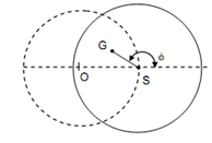
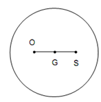
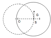
The layout of O, G and S are similar shown in Figure 9. It is the most stable condition for the rotor.
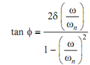
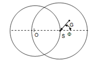
While there is damping in the shaft system, the free body diagram of the disc is illustrated in Figure 10. In this free body diagram the layout of the points O, S and G have been demonstrated. The phase angle 'φ' is specified by
This expression was derived in the previous section.
The force equation might be written as follows :
(k - m ω2 ) y = m e ω2 cos φ
And c ω y = m e ω2 sin φ
Solving the above expressions
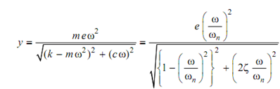
While ω > ωn, the deflection of the shaft is specified by the above expression the position of
O, S and G is illustrated in Figure.
While ω = ωn, the shaft will rotate along whirl radius equivalent to 1/2δ that is maximum.
The position of O, S and G is shown in Figure.
While ω > ωn, the deflection or whirl radius becomes less than previous case but phase angle φ is more than π . The point G tends to lie among O and S. The position of O, S and G is illustrated in Figure.