T-Section:
The method of determining the shear stress distribution in T-sections is same to that of I-section. As the T-section is not symmetrical around the neutral axis, the shear stress distribution also shall not be symmetrical.
Example
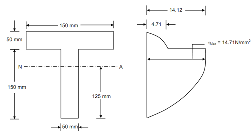
A T-section contains a flange of size 150 mm × 50 mm & web of size 50 mm × 150 mm. This section is subjected to a vertical shear force of 100 kN.
Determine the maximum shear stress & draw the shear stress distribution diagram along with values at vital points. Centroid of section is 125 mm from the bottom face & moment of inertia around the centroidal axis is 5312.5 × 104 mm4.

Beam Cross-section Shear Stress Distribution
Solution
Maximum shear stress takes place at the neutral axis.
Therefore, τmax = ( F/ Ib) × A y
= (100 × 1000 / 5312.5 × 104 × 50)[(150 × 50) × 50 + (50 × 25) × 12.5]
= 14.71 N/mm2
In the flange shear stress at the junction of flange & web,
= (100 × 1000/5312.5 × 104 × 150) × (150 × 50 × 50)
= 4.71 N/mm2
In the web shear stress at the junction of flange & web,
= (100 × 1000/5312.5 × 104 × 50) × (150 × 50 × 50)
= 14.12 N/mm2
The shear stress distribution is illustrated in Figure.