Parallel Resonance:
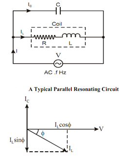
Given figure represents a parallel resonating circuit where a coil is connected in parallel with a capacitor C and the combination is connected across an AC voltage source of variable frequency. Figure represents the vector diagram of the given circuit.

Vector Diagram of the Parallel AC Circuit
Let IC = The current through the capacitor,
IL = The current through the coil,
I = Vector sum of IL and IC, that is the source current,
V = Supply voltage, VR = Drop across R, VL = Drop across L, VC = Drop across C,
φ = p.f. angle of the coil (i.e. the angle of lag of IL with respect to V),
ZL = Coil impedance, and
XC = Capacitor impedance (or simple capacitor reactance).
Here IC = V/ XC
And

cos φ= R/ Z
At resonance the capacitive current should be equal to the inductive part of the coil current, that means the imaginary components of IL and IC should cancel each other at resonance.
i.e. IC = I L sin φ
or V / X C = ( V / Z L) × (X L/ Z L)
where sin φ= X L / Z L ,
or (Z L )2 = XC XL
Also

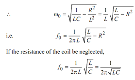
[ω0 represents resonance frequency]
or 
(ωo )2L2 = (L/C)-R2
i.e. (ωo )2L2 = (1/ LC)-R2 /L2

Again, at resonance, as the reactive components of IL and LC balance each other, the only remaining part of the current is IL cos φ (= I)
I = I L cos φ
or,
V / ZΩ = V/ Z L . (R / Z L) [ZΩ = equivalent impedance of parallel circuit.]
or,
Z Ω =( Z L)2 /R = (L/C )/R = L/(CR) [? ZL = √(L/C)]
Then, the equivalent impedance of the parallel resonating circuit is L/CR at resonance. This impedance is called as dynamic resistance of the parallel circuit. In general R being loss, this impedance is extremely high at resonance and then the current is much lower in the parallel circuit. Then, this circuit is also called as rejector circuit.