Transmission between Computing Devices
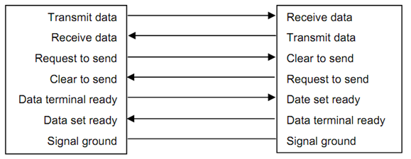
To facilitate the transmission between the two devices, there need to be some form of communicating method to establish the mutual readiness to communicate and receive data which is termed as hand shaking. Typical hand shaking methods used in the devices are shown in Figure 2. The equipment that would be sending the data will inform the equipment that would be receiving, that it is ready to send data by making the request to send line high. Upon sensing this, the receiving equipment will need to say its readiness by making the corresponding line, in this case, clear to send line high. After that the transmission can start. The same approach can be done with the data terminal ready and the data set ready lines.

DATA TERMINAL EQUIPMENT DATA COMMUNICATION EQUIPMENT
Figure 2 : Hand Shaking Methods between Communicating Devices
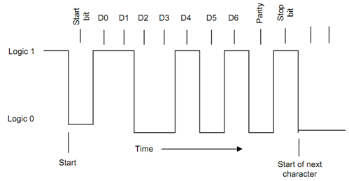
When the data is being sent as individual characters (for instance the ASCII, American Standard Code for Information Interchange code), it is necessary to communicate with the receiving equipment as to when the character is starting and when it is ending. This is done along with the help of a single start bit in the beginning and 1 or 2 stop bits at the end of the actual character transmission. Thus the full transmission of a single character requires a start bit, data bits (5 to 8), parity bit (odd, even or none to error check the correctness of data transmission), and stop bits (1, 1.5 or 2). This is schematically displayed in diagram 3. The actual data shown in Figure 3 is for the character S (1010011), with 7 data bits, even parity and one stop bit.

Figure 3 : Serial Transmission Protocol
In order for the receiving end to count the bits correctly, it is necessary to establish the speed with which the bits are being transmitted, which is termed as baud rate and is measured in bits per second. The baud rates which are usually employed are 110, 150, 300, 600, 1200, 2400, 4800, 9600, 19200, etc. The accepted standard for serial transmission is the RS 232-C of the Electronics Industry Association or EIA.
Usually, the length of the cable connecting the two devices is limited owing to the loss of data and the probability of noise. While the data requires to be transmitted over long distances, after that the signal may be converted to appropriate form so that the common telephone lines could be used for the transmission. This is done with the help of a modem (modulator - demodulator) as shown in Figure 4. The modem converts the digital data into analogue oscillations of two distinct frequencies for communicating over the telephone lines which are generally used for transmitting voice. At the receiving end, the modem demodulates and converts it back to digital 0's and 1's.

Figure 4 : Typical Transmission using a Modem Over Long Distances