Counters:
Asynchronous (Ripple) Counters
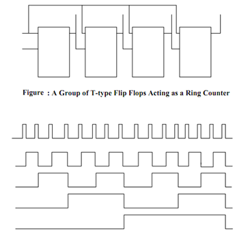
Assume a chain of four T-type Flip Flop with the output Q of each of stage connected to the clock input of the following T Flip Flop as illustrated in Figure. The pulses to be counted are applied to the clock input of the first Flip Flop. Here the T input for all the Flip Flops is tied to 1 therefore it behaves as Toggle Flip Flop. Q1 changes state at the falling edge of each pulse. All other Q's make changes its state's only when the Flip Flop modify from 1 to 0. This negative transition "ripples" through the counter from the LSB to the MSB. This shall be clearer from the waveform chart given in Figure and Table lists the states of all the binaries of the ripple counter. Let us see how to draw this waveform chart of Figure. Knowing that the Q1 modify its state at the negative transition of clock pulse we may draw the waveform for output Q1. Knowing that the Q2 modify its state at the negative transition of Q1 we may draw the waveform for output Q2 and so on. Let us see how to read this waveform to obtain the binary count number. Let us suppose that the 4th pulse is already given to Clock input of the Ripple Counter, then we may read the binary count as 0100 (decimal value is 4) as illustrated in Figure. Likewise after the 5th pulse is given to Clock input of Figure we may read the binary count as 0101 (decimal value is 5). So fundamentally it is up counting the binary numbers.

Figure: Waveform Chart of Four-stage Ripple Counter
Table: States of Flip Flops for Ripple Counter
|
No. of Input
Pulses
|
Flip Flop Outputs
|
|
Q4
|
Q3
|
Q2
|
Q1
|
|
0
|
0
|
0
|
0
|
0
|
|
1
|
0
|
0
|
0
|
1
|
|
2
|
0
|
0
|
1
|
0
|
|
3
|
0
|
0
|
1
|
1
|
|
4
|
0
|
1
|
0
|
0
|
|
5
|
0
|
1
|
0
|
1
|
|
6
|
0
|
1
|
1
|
0
|
|
7
|
0
|
1
|
1
|
1
|
|
8
|
1
|
0
|
0
|
0
|
|
9
|
1
|
0
|
0
|
1
|
|
10
|
1
|
0
|
1
|
0
|
|
11
|
1
|
0
|
1
|
1
|
|
12
|
1
|
1
|
0
|
0
|
|
13
|
1
|
1
|
0
|
1
|
|
14
|
1
|
1
|
1
|
0
|
|
15
|
1
|
1
|
1
|
1
|
|
16
|
0
|
0
|
0
|
0
|