Transconductance:
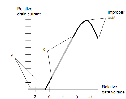
The JFET analog is termed as dynamic mutual conductance or trans-conductance. The figure is as shown below. Assume that EG is an assured value, with a corresponding ID which flows as an outcome. When the gate voltage changes by a small quantity ΔEG, then the drain current will also change by an assured increment ΔID. The trans-conductance is the ratio of ΔID/ΔEG. Geometrically, this translates to the slope of a line tangent to the curve of figure shown below at any point.
The value of ΔID/ΔEG is not similar everywhere all along the curve. Whenever the JFET is biased beyond pinchoff, as in the area marked Y in the figure given below, the slope of the curve is zero. There is no drain current, even when the gate voltage changes. Only when the channel conducts a little current will there be a change in ID whenever there is a change in EG. The area where the trans-conductance is the greatest is the area marked X, where the slope of the curve is steepest. This is where nearly all amplification can be acquired. A small change in EG generates a big change in ID, which in turn causes a big variation in a resistive load located in series with the line connecting the drain to the power supply.

Figure: Associative drain current as a function of gate voltage in a hypothetical n-channel JFET.
PROBLEM:
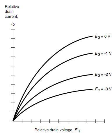
Observe the figure shown below. Note that the curves in the graph become farther not together as the drain voltage ED rises (i.e., as we move to the right). Extrapolating on this graph, it is obvious that if ED surpasses a certain level, the curves turn into horizontal lines, and they no longer extend out any farther. What can we deduce about the ability of this JFET to amplify signals as its ED rises indefinitely?

SOLUTION:
Whenever a JFET is operated at associatively low drain voltages, a certain pk-pk gate signal voltage (let say, from -2 to -1 V) generates a small change in drain current ID. Since ED rises, the curves symbolized by gate voltages EG = -2 V and EG = -1 V grow farther distant; this means that similar input signal will outcome in bigger changes in ID. This transforms into more amplification. Since ED continues to rise, the curves symbolized by EG = -2 V and EG = -1 V level off, and their separation becomes steady. The amplification factor does not rise appreciably once ED exceeds this restraining value. This similar thing will occur for all ac signals with associatively small pk-pk voltages which fall within the ranges pointed by the curves. Obviously, there is a boundary to all this. When ED becomes excessively large, then the device will be physically damaged. Most of the JFETs are designed for operation with ED values of no more than some few tens of volts.