Typical Steam Cycle
The figure shown below illustrates a simplified version of the main components of a usual steam plant cycle. This is a basic version and does not include the exact information which might be found at most of the power plants. Though, for the purpose of understanding the fundamental operation of a power cycle, further information is not essential.
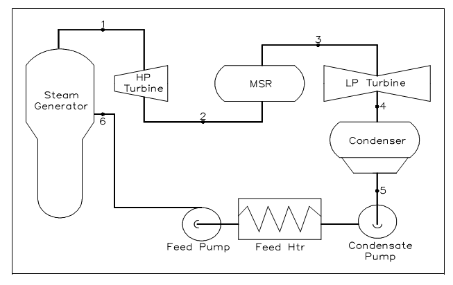
Figure: Typical Steam Cycle
The following are the procedures which comprise the cycle:
1-2: The saturated steam from steam generator is expanded in the high pressure (HP) turbine to offer shaft work output at constant entropy.
2-3: The moist steam from the outlet of the HP turbine is dried up and superheated in the moisture separator reheated (MSR).
3-4: The superheated steam from MSR is expanded in the low pressure (LP) turbine to offer shaft work output at constant entropy.
4-5: The steam exhaust from turbine is condensed in the condenser in which heat is transmitted to the cooling water under a constant vacuum situation.
5-6: The feed-water is condensed as a liquid by the condensate and feed-water pump and the feed-water is pre-heated by the feed-water heaters.
6-1: Heat is added to the functioning fluid in the steam generator under a constant pressure situation.
The earlier cycle can also be symbolized on a T-s diagram as was done with the ideal Carnot and Rankine cycles. This is shown in figure below. The numbered points on the cycle communicate to the numbered points on the figure shown below.
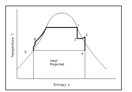
Figure: Steam Cycle (Ideal)
It should be pointed out that the cycle we have just shown is an ideal cycle and does not precisely symbolize the actual procedures in the plant. The turbine and pumps in a perfect cycle are ideal pumps and turbines and thus do not display a rise in entropy across them. Real pumps and turbines would display an entropy rise across them.
The figure shown below is a T-s diagram of a cycle which more closely estimates actual plant procedures. The pumps and turbines in this cycle are more closely estimated real pumps and turbines and therefore exhibit an entropy rise across them. In addition, in this cycle, a small degree of sub-cooling is evident in the condenser as shown by the small dip down to point 5. This small quantity of sub-cooling will reduce cycle efficiency as additional heat has been eliminated from the cycle to the cooling water as heat discarded. This additional heat discarded should then be made up for in the steam generator. Hence, it can be seen that extreme condenser sub-cooling will reduce cycle efficiency. By managing the temperature or flow rate of the cooling water to the condenser, and the operator can directly affect the overall cycle efficiency.
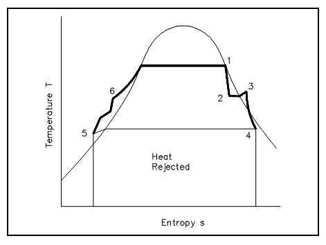
Figure: Steam Cycle (Real)