Power Plant Components
In order to examine a whole power plant steam power cycle, it is first essential to examine the elements that make up such cycles. (The figure is as shown below) However specific designs vary, there are three fundamental kinds of elements in power cycles, (A) turbines, (B) pumps and (C) heat exchangers. Related with each of these three kinds of elements is a characteristic transform in the properties of the working fluid.
We have computed system effectiveness by knowing the temperature of the heat sink and the heat source. It is also likely to compute the efficiencies of each separate component.
The effectiveness of each kind of component can be computed by comparing the real work generated by the component to the work that would have been generated by a perfect component operating isentropically among the similar inlet and outlet circumstances.
The steam turbine is designed to take out energy from the working fluid (i.e., steam) and employ it to do work in the form of revolving the turbine shaft. The functioning fluid does work as it expands via the turbine. The shaft work is then transformed to electrical energy by the generator. In the purpose of the first law, general energy equation to the simple turbine under steady flow situations, it is found that reduce in the enthalpy of the working fluid Hin -Hout equivalents the work done by the working fluid in the turbine (Wt).
Hin - Hout - Wt
m (hin - hout) - wt
Here:
Hin = enthalpy of the functioning fluid entering the turbine (Btu)
Hout = enthalpy of the working fluid leaving the turbine (Btu)
Wt = work done by the turbine (ft-lbf)
m = mass flow rate of the working fluid (lbm/hr)
hin = specific enthalpy of the functioning fluid entering the turbine (Btu/lbm)
hout = specific enthalpy of the working fluid leaving the turbine (Btu/lbm)
wt = power of turbine (Btu/hr)
Such relationships exert whenever the potential and kinetic energy alters and the heat losses of the working fluid whereas in the turbine are negligible. For most of the practical applications, these are valid suppositions. Though, to apply such relationships, one additional definition is essential. The steady flow performance of a turbine is idealized by supposing that in an ideal situation the working fluid does work reversibly by growing at constant entropy. This defines the so-called perfect turbine. In an ideal turbine, the entropy of the working fluid incoming the turbine Sin equivalents the entropy of the working fluid leaving the turbine.
Sin =Sout
sin =sout
Here:
Sin = entropy of the working fluid entering the turbine (Btu/oR)
Sout = entropy of the working fluid leaving the turbine (Btu/oR)
sin = specific entropy of the working fluid entering the turbine (Btu/lbm -oR)
sout = specific entropy of the working fluid leaving the turbine (Btu/lbm -oR)
The main reason for defining a perfect turbine is to give a basis for analyzing the performance of turbines. The ideal turbine performs the maximum quantity of work hypothetically possible.
An actual turbine does little work since of friction losses in the blades, leak past the blades and, to the lesser level, mechanical friction. The turbine efficiency, at times termed as isentropic ηt turbine efficiency since an ideal turbine is termed as one which functions at constant entropy, is termed as the ratio of the real work done by the turbine Wt, actual to the work that would be completed by the turbine when it were an ideal or perfect turbine Wt,ideal
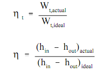
Here:
η t = turbine efficiency (no units)
Wt,actual = actual work done by the turbine (ft-lbf)
Wt,ideal = work done by an ideal turbine (ft-lbf)
(hin -hout)actual = actual enthalpy change of the working fluid (Btu/lbm)
(hin -hout)ideal = actual enthalpy change of the working fluid in an ideal turbine (Btu/lbm)
In many situations, the turbine efficiency ηt has been determined separately. This allows the real work done to be computed directly by multiplying the turbine effectiveness ηt by the work done by an ideal turbine under the similar situations. For small turbines, the turbine effectiveness is usually 60% to 80%; and for large turbines, it is usually around 90%.
The real and idealized performances of a turbine might be compared suitably by using a T-s diagram. The figure illustrates such a comparison. The ideal situation is constant entropy. It is symbolized by a vertical line on the T-s diagram. The actual turbine includes a rise in entropy. The smaller the rise in entropy, the closer the turbine efficiency ηt is to 1.0 or 100%.
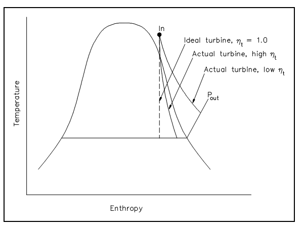
Figure: Comparison of Ideal and Actual Turbine Performances
The pump is designed to shift the working fluid by doing work on it. In the application of the first law common energy equation to a plain pump under firm flow conditions, it is found that the rise in the enthalpy of the working fluid Hout - Hin equivalents the work done by the pump, Wp , on the working fluid.
Hout - Hin - Wp
m (hout - hin) - wp
Here:
Hout = enthalpy of the working fluid leaving the pump (Btu)
Hin = enthalpy of the functioning fluid entering the pump (Btu)
Wp = work done by the pump on the working fluid (ft-lbf)
m = mass flow rate of the working fluid (lbm/hr)
hout = specific enthalpy of the working fluid leaving the pump (Btu/lbm)
hin = specific enthalpy of the functioning fluid entering the pump (Btu/lbm)
wp = power of pump (Btu/hr)
Such relationships exert whenever the kinetic and potential energy alters and the heat losses of the working fluid whereas in the pump are negligible. For most of the practical applications, these are valid suppositions. It is also supposed that the working fluid is not compressible. For the ideal situation, it can be shown that the work done by the pump Wp is equivalent to the change in enthalpy across an ideal pump.
Wp ideal = (Hout - Hin)ideal
wp ideal = (hout - hin)ideal
Here:
Wp = work done by the pump on the working fluid (ft-lbf)
Hout = enthalpy of the working fluid leaving the pump (Btu)
Hin = enthalpy of the functioning fluid entering the pump (Btu)
wp = power of pump (Btu/hr)
m = mass flow rate of the working fluid (lbm/hr)
hout = specific enthalpy of the working fluid leaving the pump (Btu/lbm)
hin = specific enthalpy of the functioning fluid entering the pump (Btu/lbm)
The cause for defining an ideal pump is to give a basis for analyzing the performance of real pumps. The pump needs more work since of inevitable losses due to friction and fluid turbulence. The work done by a pump Wp is equivalent to the change in enthalpy across the actual pump.
Wp actual = (Hout - Hin)actual
wp actual = m (hout - hin)actual
The Pump efficiency, ηp, is termed as the ratio of the work needed by the pump when it were an ideal pump wp, ideal to the actual work needed through the pump wp, actual
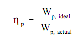
The pump efficiency, ηp, relates the work needed by an ideal pump to the actual work needed by the pump; it associates the minimum quantity of work hypothetically possible to the actual work needed by the pump. Though, the work needed by a pump is generally only an intermediate type of energy. Generally a motor or turbine is employed to run the pump. The pump efficiency does not account for losses in this turbine or motor. A further efficiency factor, motor efficiency ηm, is stated as the ratio of the actual work needed by the pump to the electrical energy input to the pump motor, whenever both are expressed in the similar units.
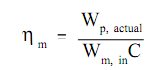
Here:
ηm = motor efficiency
Wp, actual = actual work required by the pump (ft-lbf)
Wm, in = electrical energy input to the pump motor (kw-hr)
C = conversion factor = 2.655 x 106 ft-lbf/kw-hr
Similar to pump efficiency η p, motor efficiency ηm is all the time less than 1.0 or 100% for a real pump motor. The combination of pump efficiency η p and motor efficiency ηm relates the ideal pump to the electrical energy input to the pump motor.
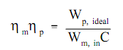
Here:
ηm = motor efficiency
ηp = pump efficiency
Wp, ideal = ideal work needed by the pump (ft-lbf)
Wm, in = electrical energy input to the pump motor (kw-hr)
C = conversion factor = 2.655 x 106 ft-lbf/kw-hr
The heat exchanger is designed to transfer heat among two working fluids. There are numerous heat exchangers employed in power plant steam cycles. In steam generator or boiler, the heat source (example, reactor coolant) is used to heat & vaporize the feed water. In the condenser, the steam exhausting from the turbine is condensed before being return to the steam generator. In adding up to these two major heat exchangers, several smaller heat exchangers are used during the steam cycle. The two primary factors determine the rate of heat transfer and the temperature difference among the two fluids passing via the heat exchanger.
In the application of the first law common energy equation to a simple heat exchanger under firm flow conditions, it is found that the mass flow rates and enthalpies of the two fluids are associated by the relationship shown below.
m1(hout,1 - hin,1) - -m2 (hout,2 - hin,2)
Here:
m1= mass flow rate of the functioning fluid 1 (lbm/hr)
m2= mass flow rate of the functioning fluid 2 (lbm/hr)
hout, 1 = specific enthalpy of the working fluid 1 leaving the heat exchanger (Btu/lbm)
hin, 1 = specific enthalpy of the working fluid 1 entering the heat exchanger (Btu/lbm)
hout, 2 = specific enthalpy of the working fluid 2 leaving the heat exchanger (Btu/lbm)
hin, 2 = specific enthalpy of the working fluid 2 entering the heat exchanger (Btu/lbm)
In this part we will apply the details to allow us to compare and compute various ideal and real cycles. This will permit us to establish how modifying a cycle will affect the cycle's available energy which can be extracted for work.
As the efficiency of a Carnot cycle is exclusively dependent on the temperature of the heat source and the temperature of the heat sink, it obeys that to improve a cycle's effectiveness all we have to do is raise the temperature of the heat source and reduce the temperature of the heat sink. In the real world the capability to do this is restricted by the constraints explain below.
1. For real cycle the heat sink is restricted by the fact that the "earth" is our last heat sink. And hence, is fixed at around 60°F (520°R).
2. The heat source is restricted to the combustion temperatures of the fuel to be burned or the maximum limits positioned on nuclear fuels by their structural components (cladding, pellets, etc.). In the situation of fossil fuel cycles the upper limit is ~3040°F (3500°R).Though even this temperature is not achievable due to the metallurgical restraints of the boilers, and hence they are limited to around 1500°F (1960°R) for a maximum heat source temperature.
By using these limits to compute the maximum efficiency achievable by an ideal Carnot cycle provides the following.
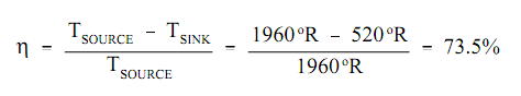
This computation points out that the Carnot cycle, operating with ideal machinery under real world constraints, must convert almost 3/4 of the input heat into work. Though, as will be shown, this ideal efficiency is fine beyond the present abilities of any real systems.