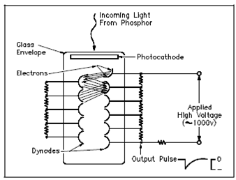
Photomultiplier Tube Schematic Diagram:
A schematic cross-section of one category of photomultiplier tube is display in above Figure. The photomultiplier is a vacuum tube along with a glass envelope holding a photocathode and a series of electrodes known as dynodes. Light from a scintillation phosphor liberates electrons from the photocathode through the photoelectric effect. These electrons are not of enough number or energy to be detected reliably through conventional electronics. Therefore, in the photomultiplier tube, they are attracted through a voltage drop of about 50 volts to the nearest dynode.

Figure: Photomultiplier Tube Schematic Diagram
The photoelectrons strike the first dynode along with enough energy to liberate various new electrons for every photoelectron. A second-generation electrons are, in turn, attracted to the second dynode where a larger third-generation group of electrons is emitted. This amplification continues by 10 to 12 stages. At the last dynode, enough electrons are available to form a current pulse appropriate for additional amplification through transistor circuits. A voltage drops among dynodes are built through a single external bias, around 1000 volts dc, and a network of external resistors to equalize the voltage drops.
The benefits of a scintillation counter are its effectiveness and the high precision and counting rates which are possible. Those latter attributes are a consequence of the very short duration of the light flashes from about 10-9 to 10-6 seconds. An intensity of the light flash and the amplitude of the outcome voltage pulse are proportional to the energy of the particle responsible for the flash. As a result, scintillation counters could be used to determine the energy, as well as the number, of the exciting particles (or gamma photons). A photomultiplier tube outcome is very meaningful in radiation spectrometry (determination of incident radiation energy levels).