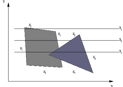
Scan Lines Crossing the Projection:
For scan lines 2 and 3 in Figure, the active edge list contains edges AD, EH, BC, and FG. Along with scan line 2 from edge AD to edge EH, only the flag for surface S1 is on. But among edges EH and BC, the flags for both surfaces are on. In this interval, depth calculations should be made using the plane coefficients for the two surfaces. For this instance, the depth of surface S1 is supposed to be less than that of S2, so intensities for surface S1 are loaded into the refresh buffer until boundary BC is encountered. After that the flag for surface S1 goes off, and intensities for surface S2, so intensities for surface S1 are loaded into the refresh buffer until boundary BC is encountered. Then the flag for surface S1 goes off, and intensities for surface S2 are stored until edge FG is passed.
We can take advantage of coherence along the scan lines as we pass one scan line to the next. In Figure, scan line 3 has the same active list of edges as scan line 2. As no changes have taken place in line intersections, it is needless again to make depth calculations between edges EH and BC. The two surfaces should be in the same orientation as determined on scan line 2, so the intensities for surface S1 may be entered without further calculations.

Figure: Scan Lines Crossing the Projection of Two Surfaces, S1 and S2, in the View Plane. Dashed Lines Indicate the Boundaries of Hidden Surfaces