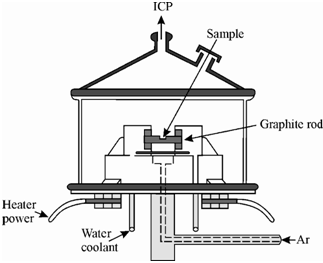
Schematic diagram of an electrothermal nebuliser:
You have also learnt about the electrothermal vaporisation and the hydride generation as the methods of introducing the sample in the atomiser. In electrothermal vaporisation method the sample is vapourised on a conductor like carbon rod or a heated metal and is carried by argon to the plasma. On the other hand in hydride generation method, a few elements are converted within volatile hydrides that are then directed into the plasma. The schematic diagram of electrothermal nebuliser used in ICP-AES is display in Figure.
Electrothermal vaporisation coupled along with a plasma torch offers the microsampling capabilities and low detection limits of electrothermal furnaces while maintaining the wide linear working range, the freedom from interference, and the multielement capabilities of ICP.

Figure: Schematic diagram of an electrothermal nebuliser for ICP-AES