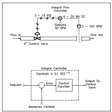
Example of an Integral Flow Control System:
Along With integral control, the last control element's position changes at a rate determined through the amplitude of the input error signal. Recall which:
Error = Setpoint - Measured Variable
A large error results if a large difference exists among the setpoint and the measured variable. This causes the last control element to change position rapidly. If, thus, only a small difference exists, the small error signal causes the last control element to change position slowly.
Above figure describes a process using an integral controller to manage a constant flow rate. Also involved is the equivalent block diagram of the controller.

Figure: Integral Flow Rate Controllers
Initially, the system is set up on an anticipated flow demand of 50 gpm that corresponds to a control valve opening of 50 Percent. Along with the setpoint equal to 50 gpm and the fact flow measured at 50 gpm, the zero error signals is sent to the input of the integral controller. A controller output is initially set for a 50%, or 9 psi, outcome to position the 6-in control valve to a position of 3 in open. The outcome rate of change of this integral controller is provided through:
Output rate of change = Integral constant x % Error
If the measured variable decreases from its initial value of 50 gpm to a new value of 45 gpm, as seen in Figure, a positive error of 5 percent is generates and applied to the input of the integral controller. A controller has a constant of 0.1 seconds-1, so the controller outcome rate of change is 0.5 percent per second.