Carnot Vapor Compression Systems:
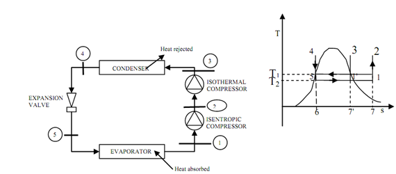
The compression is imagined here to take place in two stages: isentropic compression up to state 2 & isothermal compression from state 2 to 3 as illustrated in below described Figure (b).

(a) Schematic Representation of a Carnot Vapour Compression System (b) T-S Diagram
In a heat exchanger the working medium is condensed providing saturated liquid at state four. The isentropic expansion from state 4 to state 5 provides the refrigeration effect, the area under line 5-1.
Comparing figs.(1) and (2), we may illustrate that the Carnot vapour compression cycle provides a greater refrigeration effect than the vapour compression cycle.
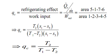
The COP of a Carnot vapour compression cycle is explained as following:

Here, T1 is the temperature at which heat is discarded in the condenser and T2 is the temperature that maintained in the evaporator. This might be illustrated that the refrigeration system functioning on the Carnot vapour compression cycle has the highest COP.