Full-Wave Rectifier:
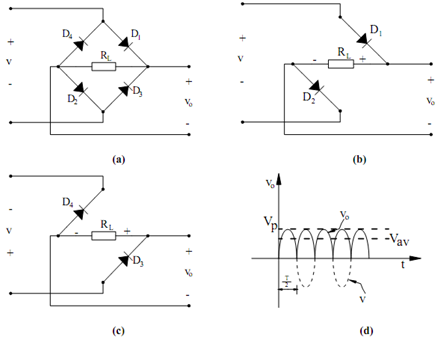
A circuit which provides a unidirectional voltage/current in both the half cycles is known as a full wave rectifier. A popular circuit uitlized for this purpose is the one illustrated in Figure (a) which is called a full-wave bridge rectifier. In this circuit, current pass in the same direction through the load resistor, for both polarities of the input voltage. It is accomplished by using two forward-biased diodes in series with RL at any time, as illustrated in Figures (b) and (c). In Figure (b), the input voltage contain a polarity that makes the top input terminal positive, thus, only the two diodes illustrated are forward biased and are conducting. As the input voltage reverses, the bottom terminal becomes positive. Now the remaining two diodes conduct, while the previous two are open circuited, as illustrated in Figure (c). Consequently, it is found that current pass through RL at all times in the same direction thereby leading to the waveform illustrated in Figure (d). It must be kept in mind that in this full-wave rectifier circuit, the two diodes are always in series with a resultant voltage drop of 1.4 V, which could be a substantial voltage drop and must be taken into account while designing a low voltage power supply.

Figure: (a) A full-wave Bridge Rectifier; (b) ,(c) Conduction Path when the Input Polarity is as Shown; and (d) Output Voltage v0 of the Full-wave Rectifier
The average voltage of full-wave rectifier is specified by following

If 120 VAC is the input voltage, the full-wave rectifier has the potential to generates twice the voltage of a half-wave rectifier, i.e. 108 VDC.