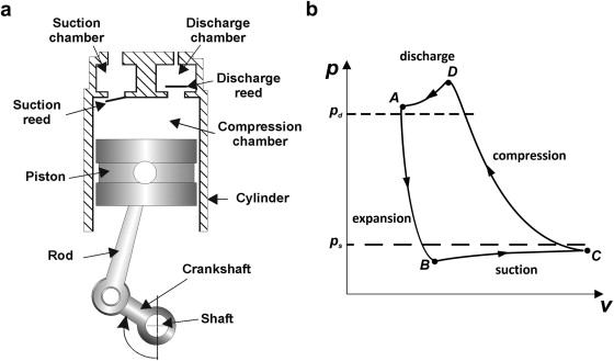
Work Of Compression-Reciprocating Compressors
The usual indicator card acquired from a reciprocating compressor is as shown in figure below.
Compression:
Beginning at maximum cylinder volume, point, a little below the inlet pressure p, as the volume reduces the pressure increases until it arrives at p2 at b; the discharge valve does not open till the pressure in the cylinder surpasses p2 by sufficient to overcome the valve spring force.
Discharge:
Among b and c gas flows out at a pressure higher than p2 by the quantity of the pressure loss via the valves; at C, the point of least volume, the discharge valve is blocked by its spring.
Expansion:
From c to d, as the volume rises, the gas staying in the clearance volume expands and its pressure falls; the suction valve does not open till the pressure falls adequately below p1 to overcome the spring force.
Intake:
Among d and a gas flows in the cylinder at a pressure lower than p1 by the quantity of pressure loss via the valve.
The total region of the diagram symbolizes the real work of the compressor on the gas. The cross-hatched regions of the diagram above p2 and below p1 symbolize work done solely since of pressure drop via the valves and port passages. This work is termed as the valve loss.
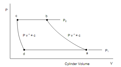
Figure: Ideal Indicator Diagram
The idealized machine to which a real machine is compared consists of an indicator diagram as shown in figure above in which there are no pressure loss effects, and the procedures a – b and c – d are reversible polytropic procedures. Supposing no state change in the intake d – a and discharge b – c procedures, and supposing equivalent values of the exponent n in the compression a – b and expansion procedures c – d, the ideal work of compression can be found by taking the integral of pdv about the diagram. When mf is the mass of fluid taken in and discharged per machine cycle, and then the total work interaction per cycle is given by,
w = wa-b + wb-c + wc-d + wd-a
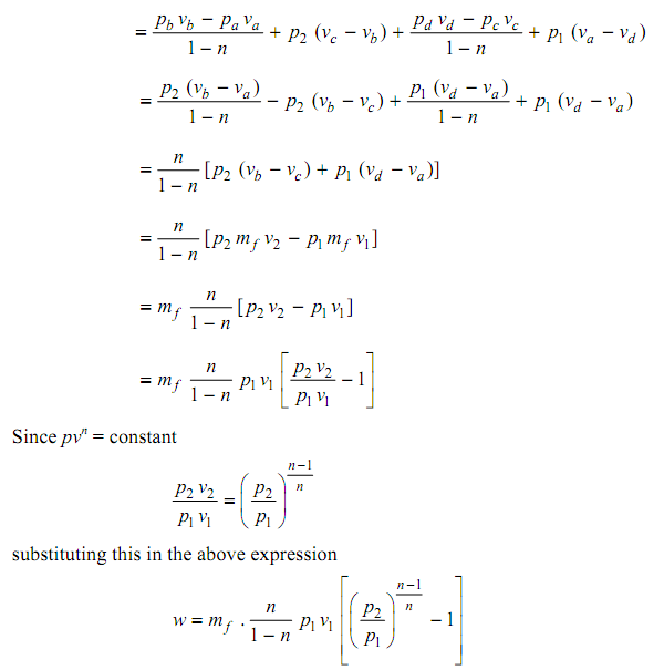
Therefore we observe that the work per kg of fluid flow is similar as acquired from the steady flow analysis. It is hence needless; to make any further analysis of the work of the idealized reciprocating compressor as all desired outputs have already been acquired by the steady flow analysis.