Analyzer Operation:
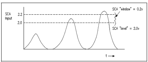
The preamplifier amplifies the voltage pulse. In addition amplification is obtained through sending the signal by an amplifier circuit (classical about 10 volts maximum). A pulse size is then determined through a single channel analyzer. Below Figure displays the operation of a single channel analyzer.

Figure: Single Channel Analyzer Operation
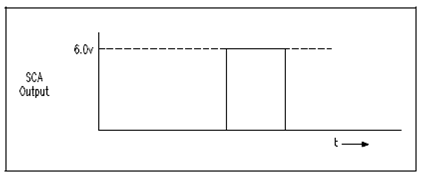
The single channel analyzer has two dial settings that are as follows: a LEVEL dial and a WINDOW dial. For instance, while the level is set at 2 volts and the window at 0.2 volts then the analyzer will provide an output pulse only while the input pulse is among 2 and 2.2 volts. The outcome pulse is commonly a standardized height and width logic pulse, as display within Figure.

Figure: Single Channel Analyzer Output
Because the single channel analyzer could be set so in which an output is only generated through a certain pulse size, it gives for the counting of one specific radiation in a mixed radiation field.
This outcome is fed to a scaler that counts the number of pulses it receives. A timer gates the scaler so in which the scaler counts the pulses for a predetermined length of time. Knowing the number of counts per provided time interval permits calculation of the count rate (number of counts per unit time).